Diagnostics
11.2 List of faults and alarms
SINAMICS V90, SIMOTICS S-1FL6
404
Operating Instructions, 04/2019, A5E36037884-007
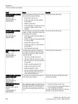
Alarm
Cause
Remedy
A1920: Drive Bus: Receive
setpoints after To
Output data of Drive Bus master (set-
points) received at the incorrect instant in
time within the Drive Bus clock cycle.
•
Check bus configuration.
•
Check parameters for clock cycle syn-
chronization (ensure To > Tdx).
Note:
To: Time of setpoint acceptance
Tdx: Data exchange time
A1932: Drive Bus clock cycle
synchronization missing for
DSC
There is no clock synchronization or clock
synchronous sign of life and DSC is se-
lected.
Note:
DSC: Dynamic Servo Control
Set clock synchronization across the bus
configuration and transfer clock synchronous
sign-of-life.
A5000: Drive heat sink over-
temperature
The alarm threshold for overtemperature at
the inverter heat sink has been reached.
If the temperature of the heat sink increas-
es by an additional 5 K, then fault F30004
is initiated.
Check the following:
•
Is the surrounding temperature within the
defined limit values?
•
Have the load conditions and the load
duty cycle been appropriately dimen-
sioned?
•
Has the cooling failed?
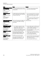
A6310: Supply voltage
(p29006) incorrectly parame-
terized
For AC/AC drive units, the measured DC
voltage lies outside the tolerance range
after precharging has been completed.
The following applies for the tolerance
range: 1.16 × p29006 < r0026 < 1.6 ×
p29006
Note:
The fault can only be acknowledged when
the drive is switched off.
•
Check the parameterized supply voltage
and if required change it (p29006).
•
Check the line supply voltage.
See also: p29006 (Line supply voltage)
A7012: Motor temperature
model 1/3 overtemperature
The motor temperature model 1/3 identi-
fied that the alarm threshold was exceed-
ed.
•
Check the motor load and reduce it if
required.
•
Check the motor surrounding tempera-
ture.
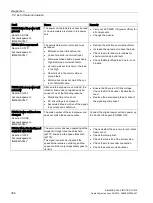
A7092: Drive: Moment of
inertia estimator still not ready
The moment of the inertia estimator has
still not determined any valid values.
The acceleration cannot be calculated.
The moment of inertia estimator has stabi-
lized, if the ratio of machine load moment
of inertia (p29022) have been determined.
Traverse the axis until the moment of inertia
estimator has stabilized.
The alarm is automatically withdrawn after the
moment of inertia estimator has stabilized.
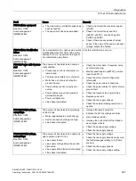
A7440: IPos: Jerk time is
limited
The calculation of the jerk time Tr = max
(p2572, p2573)/p2574 resulted in an ex-
cessively high value so that the jerk time is
internally limited to 1000 ms.
Note:
The alarm is also output if jerk limiting is
not active.
•
Increase the jerk limiting (p2574).
•
Reduce maximum acceleration or maxi-
mum deceleration (p2572, p2573).
See also: p2572 (IPos maximum accelera-
tion), p2573 (IPos maximum deceleration),
p2574 (IPos jerk limiting)


