


Control functions
7.5 Internal position control (IPos)
SINAMICS V90, SIMOTICS S-1FL6
252
Operating Instructions, 04/2019, A5E36037884-007
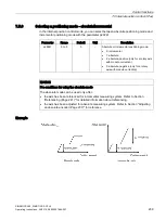
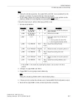
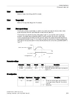
The timing diagram for starting positioning with the trigger signal P-TRG is shown as follows:
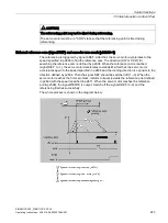
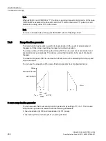
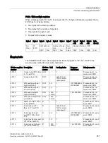
Selecting the target position and starting the positioning with the rising edge of the signal STEPF,
STEPB or STEPH
If the signal STEPF is enabled, the servo motor, at a rising edge of STEPF, traverses to next
fixed position setpoint. For example, if the servo motor currently locates at the fixed position
setpoint 3, the servo motor traverses to the fixed position setpoint 4 at a rising edge of
STEPF.
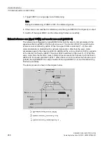
If the signal STEPB is enabled, the servo motor, at a rising edge of STEPB, traverses to
previous fixed position setpoint.
If the signal STEPH is enabled, the servo motor, at a rising edge of STEPH, traverses to the
fixed position setpoint 1.
Note
The servo drive can respond to the rising edge of the signal STEPF, STEPB or STEPH only
when the servo motor is at a standstill.
If the servo motor is at fixed position 8, a rising edge of STEPF is not responded.
If motor is at fixed position 1, a rising edge of STEPH is responded, but a rising edge of
STEPB is not responded.
During positioning, if the motor stops unexpectedly, the drive assumes that the target
position has been reached; for example, if the motor stops between POS2 and POS3
because of a fault after the signal STEPB (traversing to POS2) is given, the drive assumes
that POS2 has been reached.


