


Mounting
3.2 Mounting the motor
SINAMICS V90, SIMOTICS S-1FL6
100
Operating Instructions, 04/2019, A5E36037884-007
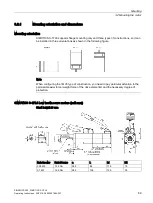
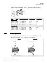
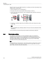
Mount or remove the power output elements (e.g. couplings, gear wheels, belt pulleys) using
suitable devices only (see figure).
●
Use the threaded hole in the shaft extension.
●
If required, heat up the output elements before mounting or removing.
●
When removing the output elements, use an intermediate disk to protect the centering in
the shaft extension.
●
If necessary, completely balance the motor together with the output elements according
to ISO 1940.
Note
Motors with feather key are half-key balanced. The motors have been balanced with half
a feather key.
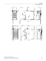
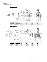
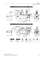
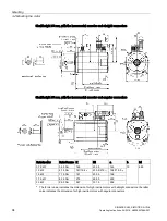
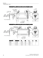
For motor dimension, see Section "Mounting orientation and dimensions (Page 89)".
3.2.4
Motor heating conditions
The rated motor specifications are continuous allowable values at a surrounding air
temperature of 40 °C when the motor is installed with a steel flange. When the motor is
mounted on a small surface, the motor temperature may rise considerably because of the
limited heat radiating abilities of the surface. Make sure that you use a suitable flange
according to Siemens-recommended flange sizes.
Note
The actual temperature rise depends on how the flange (motor mounting section) is fixed on
the installation surface, what material is used for the motor mounting section, and motor
speed. Always check the actual motor temperature.


