


Connecting
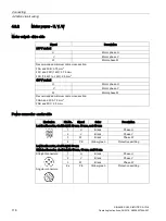
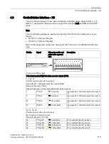
4.3 Control/status interface - X8
SINAMICS V90, SIMOTICS S-1FL6
120
Operating Instructions, 04/2019, A5E36037884-007
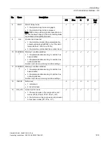
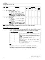
Pin No.
Signal
Wire color on the set-
point cable exposed
side
Description
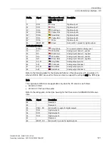
15, 16, 40, 41:
Encoder emulation pulse output with high-speed 5 V differential signals (A+/A-, B+/B-)
15
PTOA+
White-Yellow
High-speed 5 V differential pulse train en-
coder output A (+)
16
PTOA-
Yellow-Brown
High-speed 5 V differential pulse train en-
coder output A (-)
40
PTOB+
Gray-Blue
High-speed 5 V differential pulse train en-
coder output B (+)
41
PTOB-
Pink-Blue
High-speed 5 V differential pulse train en-
coder output B (-)
17, 25 *:
Encoder Zero phase pulse output and reference ground (with open collector)
17
PTOZ (OC)
White-Gray
Pulse train encoder output Z signal (open
collector output)
25 *
PTOZ_M (OC)
Gray-Green
Pulse train output Z signal reference ground
(open collector output)
42, 43:
Encoder Zero phase pulse output with high-speed 5 V differential signals
42
PTOZ+
Gray-Red
High-speed 5 V differential pulse train en-
coder output Z (+)
43
PTOZ-
Pink-Red
High-speed 5 V differential pulse train en-
coder output Z (-)
24 *:
PTO and PTI_D reference ground
24 *
M
Brown-Red
PTO and PTI_D reference ground
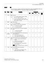
Digital inputs/outputs
3
DI_COM
Green
Common terminal for digital inputs
4
DI_COM
Yellow
Common terminal for digital inputs
5
DI1
Gray
Digital input 1
6
DI2
Pink
Digital input 2
7
DI3
Blue
Digital input 3
8
DI4
Red
Digital input 4
9
DI5
Black
Digital input 5
10
DI6
Violet
Digital input 6
11
DI7
White
Digital input 7
12
DI8
Brown
Digital input 8
13
DI9
White-Green
Digital input 9
14
DI10
Brown-Green
Digital input 10
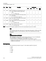
23
Brake
White-Red
Motor holding brake control signal (for
SINAMICS V90 200 V variant only)
28
P24V_DO
Yellow-Gray
External 24 V supply for digital outputs
29 *
DO4+
Green
Digital output 4+
30
DO1
Yellow
Digital output 1


