


Parameters
10.2 Parameter list
SINAMICS V90, SIMOTICS S-1FL6
368
Operating Instructions, 04/2019, A5E36037884-007
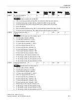
Par. No.
Name
Min
Max
Factory
Setting
Unit Data
type
Effective
Can be
changed
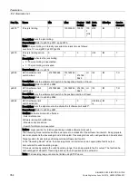
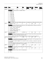
p29243
Positioning tracking acti-
vate
0
1
0
-
I16
IM
T
Description: Activation of position tracking.
•
0: Deactivated
•
1: Activated
p29244
Absolute encoder virtual
rotary revolutions
0
4096
0
-
U32
IM
T
Description: Sets the number of rotations that can be resolved for an encoder with activated position tracking
function (p29243 = 1).
p29245
Axis mode state
0
1
0
-
U32
IM
T
Description: Linear/modulo mode:
•
0: Linear axis
•
1: Modulo axis
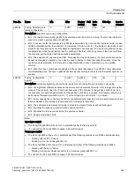
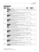
p29246 * Modulo correction range 1
214748264
7
360000 LU U32
IM
T
Description: Sets the modulo range for axes with modulo correction.
p29247 * Mechanical gear: LU per
revolution
1
214748364
7
10000 -
U32
IM
T
Description: LU per load revolution.
p29248 * Mechanical gear: Numer-
ator
1
1048576
1
-
U32
IM
T
Description: (Load/Motor) Load revolutions.
p29249 * Mechanical gear: denom-
inator
1
1048576
1
-
U32
IM
T
Description: (Load/Motor) Motor revolutions.
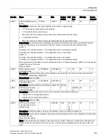
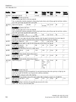
p29250
PTI absolute position
mode enable
0
1
0
-
U32
RE
T
Description: Absolute position mode enable.
•
1: Enable Absolute Mode
•
0: Disable Absolute Mode
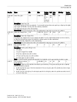
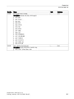
p29300
Digital input forced sig-
nals
0
127
0
-
U32
IM
T, U
Description: assignment signals are forced to be high. 7 bits in total.
•
Bit 0: SON
•
Bit 1: CWL
•
Bit 2: CCWL
•
Bit 3: TLIM1
•
Bit 4: SPD1
•
Bit 5: TSET
•
Bit 6: EMGS
If one or more bits are set to be high, the corresponding input signals are forced to be logical high signals.
Note: The drive unit displays the value in hex format. To know the logic (high/low) assignment to each bit, you
must convert the hex number to the binary number, for example, FF (hex) = 11111111 (bin).


