


Connecting
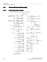
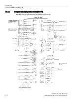
4.3 Control/status interface - X8
SINAMICS V90, SIMOTICS S-1FL6
134
Operating Instructions, 04/2019, A5E36037884-007
Pin No. Analog input
Input voltage
Control mode
Function
21, 22
Analog input
2
0 V to 10 V
Fast PTI
Torque limit (reference r0333)
0 V to 10 V
PTI
Torque limit (reference r0333)
0 V to 10 V
IPos
Torque limit (reference r0333)
0 V to 10 V
S
Torque limit (reference r0333)
-10 V to +10 V
T
Torque setpoint (reference r0333)
* If the AI input voltage is higher than 10 V, the speed is not limited to the value at 10 V (p29060), but
scaled according to p29060. For example, if p29060 = 3000 rpm, the speed is 3300 rpm at 11 V and
3600 rpm at 12 V.
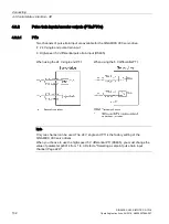
Command voltage
The command voltage of the analog inputs always follows the formula below:
V
input
= (AI+) - (AI-)
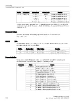
4.3.3.2
AOs
The SINAMICS V90 has two analog outputs. You can find detailed information about these
two analog outputs from the table below:
Pin No.
Analog output
Output voltage
Function
46
Analog output 1
-10 V to +10 V
Analog output 1 for monitoring
48
Analog output 2
-10 V to +10 V
Analog output 2 for monitoring
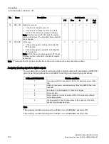
Parameterization
Two parameters, p29350 (selects signal sources for AO1) and p29351 (selects signal
sources for AO2), are used to select the source of analog output:
Parameter
Value
Source
p29350
0 (default)
Actual speed (reference p29060)
1
Actual torque (reference 3 × r0333)
2
Speed setpoint (reference p29060)
3
Torque setpoint (reference 3 × r0333)
4
DC bus voltage (reference 1000 V)
5
Pulse input frequency (reference 1 k)
6
Pulse input frequency (reference 10 k)
7
Pulse input frequency (reference 100 k)
8
Pulse input frequency (reference 1000 k)
9
Remaining number of pulses (reference 1 k)
10
Remaining number of pulses (reference 10 k)
11
Remaining number of pulses (reference 100 k)
12
Remaining number of pulses (reference 1000 k)