Mounting
3.2 Mounting the motor
SINAMICS V90, SIMOTICS S-1FL6
Operating Instructions, 04/2019, A5E36037884-007
99
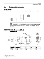
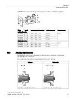
Install the motor onto a steel flange with four screws as shown in the following figure:
Motor
Screw
Recommended flange size
Tightening torque
Flange material
Low inertia motors
1FL602❑
2 x M4
120 x 100 x 40 (mm)
2.4 Nm
Steel
1FL603❑
4 x M5
120 x 100 x 40 (mm)
4.7 Nm
1FL604❑
4 x M6
120 x 100 x 40 (mm)
8 Nm
1FL605❑
4 x M8
120 x 100 x 40 (mm)
20 Nm
High inertia motors
1FL604❑
4 x M6
270 x 270 x 10 (mm)
8 Nm
Steel
1FL606
❑
4 x M8
390 x 390 x 15 (mm)
20 Nm
1FL609❑
4 x M12
420 x 420 x 20 (mm)
85 Nm
3.2.3
Attaching output elements
Reduce the bending torque load applied to the shaft and the bearing by appropriately
arranging the output elements.
Mount the output elements as close as possible to the motor bearing.
Optimum
Unfavorable
Low stress on shafts and bearings
High stress on shafts and bearings

