Commissioning
5.3 Commissioning in pulse train position control mode (PTI)
SINAMICS V90, SIMOTICS S-1FL6
Operating Instructions, 04/2019, A5E36037884-007
179
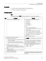
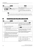
Step
Description
Comment
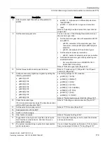
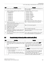
8
Select a pulse input channel by setting parameter
p29014.
•
p29014 = 0: high-speed 5 V differential pulse train
input (RS485)
•
p29014 = 1 (default): 24 V single end pulse train
input
Refer to "Selecting a setpoint pulse train input channel
(Page 222)".
9
Set the electronic gear ratio.
You can use one of the following three methods to set
the electronic gear ratio:
•
Set the electronic gear ratio with parameters p29012
and p29013.
–
p29012: numerator of the electronic gear. Four
numerators in total (p29012[0] to p29012[3]) are
available.
–
p29013: denominator of the electronic gear.
•
Set the setpoint pluses per revolution.
–
p29011: number of setpoint pulses per revolution.
•
Calculate the electronic gear ratio by selecting me-
chanical structure.
–
For more information, see SINAMICS V90 V-
ASSISTANT Online Help.
Refer to "Electronic gear ratio (Page 225)".
10 Set the torque limitation and speed limitation.
Refer to "Torque control (T) (Page 261)" and "Speed
control (S) (Page 256)".
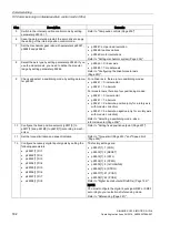
11 Configure necessary digital input signals by setting the
following parameters:
•
p
29301[0]: DI1
•
p29302[0]: DI2
•
p29303[0]: DI3
•
p29304[0]: DI4
•
p29305[0]: DI5
•
p29306[0]: DI6
•
p29307[0]: DI7
•
p29308[0]: DI8
The factory settings for PTI mode are:
•
p29301[0]: 1 (SON)
•
p29302[0]: 2 (RESET)
•
p29303[0]: 3 (CWL)
•
p29304[0]: 4 (CCWL)
•
p29305[0]: 5 (G
-CHANGE)
•
p29306[0]: 6 (P
-TRG)
•
p29307[0]: 7 (CLR)
•
p29308[0]: 10 (TLIM1)
Refer to "Digital inputs/outputs (DIs/DOs) (Page 122)".
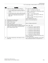
12 Check the encoder type.
If it is an absolute encoder, adjust the absolute encoder
with the BOP menu function "ABS".
Refer to "Adjusting an absolute encoder (Page 207)".
13 Set the pulse train encoder output.
Refer to "PTO function (Page 234)".
14 Save parameters with the BOP.
15 Switch on the line supply.
16 Clear faults and alarms.
Refer to "Diagnostics (Page 383)".
17 Trigger SON to the high level, input the setpoint pulse
train from the command device, and then the servo
motor starts running.
Use a low pulse frequency at first to check the direction
and speed of rotation.
18 The system commissioning in pulse train input position
control mode ends.
You can check the system performance. If it is not satis-
fied, you can adjust it. Refer to "Tuning (Page 313)".

