Parameters
10.2 Parameter list
SINAMICS V90, SIMOTICS S-1FL6
378
Operating Instructions, 04/2019, A5E36037884-007
Par. No.
Name
Unit
Data type
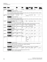
r0632
Motor temperature model, stator winding temperature
°C
Float
Description: Displays the stator winding temperature of the motor temperature model.
r0722
CU digital inputs status
-
U32
Description: Displays the status of the digital inputs.
Note:
DI: Digital input
DI/DO: Bidirectional digital input/output
The drive unit displays the value in hex format. You can convert the hex number to the binary number, for
example, FF (hex) = 11111111 (bin).
r0747
CU digital outputs status
-
U32
Description: Displays the status of digital outputs.
Note:
DI/DO: Bidirectional digital input/output
The drive unit displays the value in hex format. You can convert the hex number to the binary number, for
example, FF (hex) = 11111111 (bin).
r0807.0
Master control active
-
U8
Description: Displays what has the master control. The drive can be controlled via the internal interconnection
or from external.
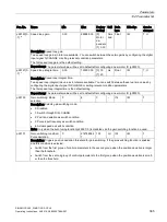
r0945[0...6
3]
Fault code
-
U16
Description: Displays the number of faults that have occurred.
Dependency: Refer to r0949
Note: The buffer parameters are cyclically updated in the background.
Fault buffer structure (general principle):
r0945[0], r0949[0] → actual fault case, fault 1
...
r0945[7], r0949[7] → actual fault case, fault 8
r0945[8], r0949[8] → 1st acknowledged fault case, fault 1
...
r0945[15], r0949[15] → 1st acknowledged fault case, fault 8
...
r0945[56], r0949[56] → 7th acknowledged fault case, fault 1
...
r0945[63], r0949[63] → 7th acknowledged fault case, fault 8
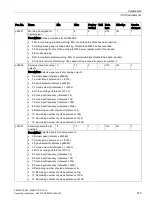
r0949[0...6
3]
Fault value
-
I32
Description: Displays additional information about the fault that occurred (as integer number).
Dependency: Refer to r0945
Note: The buffer parameters are cyclically updated in the background.
The structure of the fault buffer and the assignment of the indices is shown in r0945.
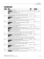
r2050
[0...19]
MODBUS PZD receive word
-
I16
Description: Modbus PZD (setpoints) with word format received from the host controller.
Index:
Index 0 to index 19 stand for PZD1 to PZD20 correspondingly.
•
[0]: Control word from host controller, the definition of control word refer to r2090.
•
[1]: In speed control mode, means speed setpoint from
host controller.
•
[2] and [3]: In internal position control mode, means position setpoint(Hword/Lword) from host controller
•
[4] to [19]: Reserved.

