System Overview 1-17
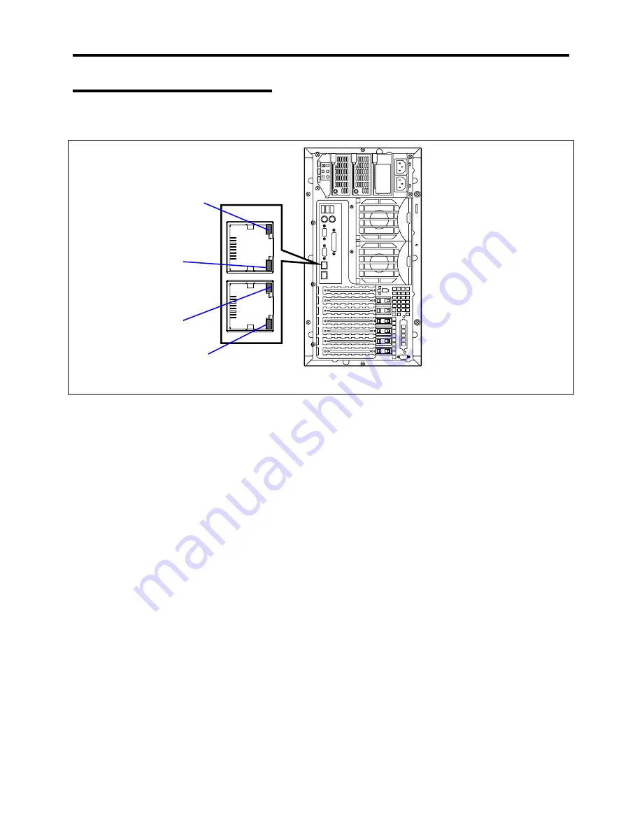
LAN Connector LEDs
There are two LEDs for each of the two LAN ports (connectors) on the rear panel.
LINK/ACT LED
1000/100/10 LED
LINK/ACT LED
1000/100/10 LED
!
LINK/ACT LEDs
Each LINK/ACT LED indicates the status of the standard network port of the server.
While power is supplied to the server and HUB and the connection is correct, the LED is
on (green). The LED turns green and flashes while the network port is
transmitting/receiving data. (ACT)
If the LED does not go on when the port is connected to the LAN port, check the network
cable. If the LED does not go on and the network cable has checked out OK, the network
(LAN) controller may be faulty. In this case, contact your sales representative.
!
1000/100/10 Speed LEDs
The Speed LED indicates that the communication mode of the server is activated with
either a network interface of 1000 BASE-T, 100BASE-TX or 10BASE-T. When the LED
is amber, it indicates that the communication mode is activated with 1000BASE-T. Data
transfer rate is 1000Mb/s. When the LED is on green, it indicates that the communication
mode is activated with 100BASE-TX. Data transfer rate is 100Mb/s. When the LED is off,
it indicates that the communication mode is activated with 10BASE-T.
Data transfer rate is
10Mb/s.
Summary of Contents for EXPRESS5800/120MF
Page 1: ... EXPRESS5800 120Mf U s e r s G u i d e ...
Page 2: ......
Page 4: ......
Page 12: ...x ...
Page 24: ...1 6 System Overview Rear View 11 9 10 12 13 14 15 16 2 17 15 18 17 16 1 8 7 6 1 2 3 4 5 2 5 1 ...
Page 58: ...1 40 System Overview This page is intentionally left blank ...
Page 59: ...Chapter 2 Setting Up Your Server This chapter describes how to set up your server ...
Page 202: ...4 62 Installing the Operating System and Utilities This page is intentionally left blank ...
Page 214: ...5 12 Maintenance This page is intentionally left blank ...
Page 229: ...Troubleshooting 6 15 Memory modules DIMM Group 3 DIMM Group 2 DIMM Group 1 ...
Page 304: ...7 50 Upgrading your Server This page is intentionally left blank ...
Page 305: ...Chapter 8 Internal Cabling Diagrams Internal cable connections of the server are shown below ...
Page 318: ...B 4 IRQ and I O Port Address This page is intentionally left blank ...
Page 326: ...C 8 Installing Windows 2000 This page is intentionally left blank ...
Page 340: ...10 Glossary This page is intentionally left blank ...
Page 345: ...xx ...
Page 346: ... ...


