2-32 Setting Up Your System
CONNECTING PERIPHERAL DEVICES
Connect peripheral devices to the server. The server is provided with connectors on its front and
rear for a wide variety of peripheral devices. The figure on the next page illustrates available
peripheral devices for the server in the standard configuration as well as the locations of the
connectors for such devices.
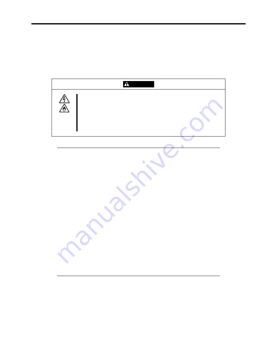
CAUTION
Observe the following instructions to use the server safely. Failure to follow
these instructions may cause a fire, personal injury, or property damage.
■
Do not use any damaged cable connector.
■
Do not use any unauthorized interface cable.
■
Do not use the server with any loose interface connection.
■
Do not connect any interface cable with the power cord of the Express server
plugged to a power source..
IMPORTANT:
!
Power off the server and a peripheral device before connection.
Connecting a powered peripheral device to the powered server will
cause malfunctions and failures.
!
To connect a third-party peripheral device or interface cable to the server,
consult with your service representative for availability of such a device
or cable. Some third-party devices may not be used with the server.
!
The total length of a cable (including the connection cable in SCSI
device) is limited by the SCSI standard. Ask your sales representative
for details. (The internal cable of the server is 0.5 m long.)
!
To use the external SCSI port, see Chapter 8 for changing the internal
cable connection.
!
Make sure that no SCSI IDs for external SCSI devices and internal
devices conflict.
!
A leased line cannot be connected directly to the serial port connectors.
!
Secure the power cord(s) and interface cables with a tie wrap.
!
Form the cables in such a way that they will not come into contact with
the door or the guide rails on the sides of the server.
Summary of Contents for EXPRESS5800/120MF
Page 1: ... EXPRESS5800 120Mf U s e r s G u i d e ...
Page 2: ......
Page 4: ......
Page 12: ...x ...
Page 24: ...1 6 System Overview Rear View 11 9 10 12 13 14 15 16 2 17 15 18 17 16 1 8 7 6 1 2 3 4 5 2 5 1 ...
Page 58: ...1 40 System Overview This page is intentionally left blank ...
Page 59: ...Chapter 2 Setting Up Your Server This chapter describes how to set up your server ...
Page 202: ...4 62 Installing the Operating System and Utilities This page is intentionally left blank ...
Page 214: ...5 12 Maintenance This page is intentionally left blank ...
Page 229: ...Troubleshooting 6 15 Memory modules DIMM Group 3 DIMM Group 2 DIMM Group 1 ...
Page 304: ...7 50 Upgrading your Server This page is intentionally left blank ...
Page 305: ...Chapter 8 Internal Cabling Diagrams Internal cable connections of the server are shown below ...
Page 318: ...B 4 IRQ and I O Port Address This page is intentionally left blank ...
Page 326: ...C 8 Installing Windows 2000 This page is intentionally left blank ...
Page 340: ...10 Glossary This page is intentionally left blank ...
Page 345: ...xx ...
Page 346: ... ...


