7-22 Upgrading your Server
Power Supply
The addition of a third hot-swap power supply makes your system so that it has redundant power
and can be operated continuously without interruption if either of the power supplies malfunction.
Installation
To install the optional hot-swap power supply, perform the following procedures:
1.
See the section
Preparing for Upgrade
described earlier in this chapter.
2.
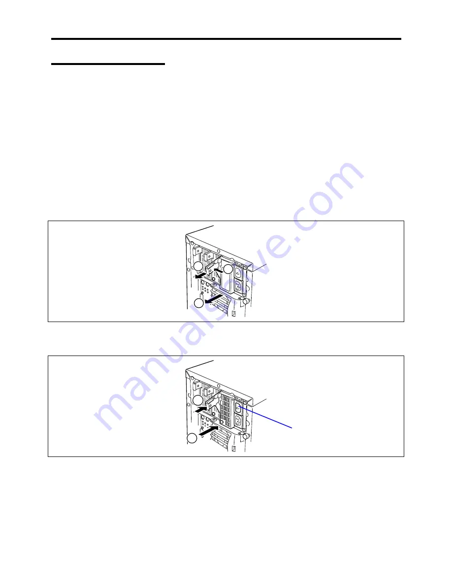
At the rear of the cabinet locate the power supply bay, (with a blank cover over it), where
the optional power supply will be installed.
3.
Remove the blank cover by grasping its handle (1) with your right hand, press the latch
with your index finger, pull the handle down slightly (2), and slide the cover out of the bay
(3). Save the blank cover for future use.
1
2
3
4.
Slide the new power supply into the bay until its latch clicks into place.
5.
Using pliers, remove the dust cover from the second AC inlet.
2
1
Dust cover
6.
Connect two power cords to the AC inlets.
Use the standard power cord coming with the server and the cord coming with the power
supply.
7.
Turn on the system.
The AC power LEDs on the power supplies are lit. When the server is in redundant power
supply configuration, the ACR LED on the rear of the server lights up.
Summary of Contents for EXPRESS5800/120MF
Page 1: ... EXPRESS5800 120Mf U s e r s G u i d e ...
Page 2: ......
Page 4: ......
Page 12: ...x ...
Page 24: ...1 6 System Overview Rear View 11 9 10 12 13 14 15 16 2 17 15 18 17 16 1 8 7 6 1 2 3 4 5 2 5 1 ...
Page 58: ...1 40 System Overview This page is intentionally left blank ...
Page 59: ...Chapter 2 Setting Up Your Server This chapter describes how to set up your server ...
Page 202: ...4 62 Installing the Operating System and Utilities This page is intentionally left blank ...
Page 214: ...5 12 Maintenance This page is intentionally left blank ...
Page 229: ...Troubleshooting 6 15 Memory modules DIMM Group 3 DIMM Group 2 DIMM Group 1 ...
Page 304: ...7 50 Upgrading your Server This page is intentionally left blank ...
Page 305: ...Chapter 8 Internal Cabling Diagrams Internal cable connections of the server are shown below ...
Page 318: ...B 4 IRQ and I O Port Address This page is intentionally left blank ...
Page 326: ...C 8 Installing Windows 2000 This page is intentionally left blank ...
Page 340: ...10 Glossary This page is intentionally left blank ...
Page 345: ...xx ...
Page 346: ... ...


