FX Series Positioning Controllers
Wiring 3
3-11
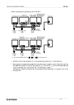
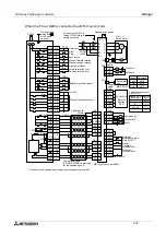
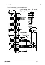
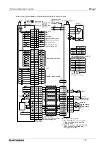
3.2.4
Drive system/mechanical system I/O wiring
SV
END
P
P
P
P
P
P
3
3
3
1
1
1
SV
RDY
CLR
13
16
6
PGO
RP
FP
13
16
6
13
16
6
67
8
LSF
LSR
DOG
16
18
17
6
8
7
CON3
CON4
CON1
X axis
Y axis
FX
2N
-10GM
CON2
10GM
FX
2N
-20GM
Positioning unit
Either FP and RP or PLS
and SIGN are output
depending on parameter
settings. The output must
match the input format of
the drive unit.
CON2
CON2
VIN
7.81 7.18
5 to 24V DC
Power surply
7.81 7.18
7.81 7.18
Ma
chine zero
retu
rn control
After the near-point signal is turned ON, deceleration
is started. When the specified number of zero point
signals are detected, zero return is completed.
Then, the clear signal is outpur to clear the deviation
counter. The automatic DOG search function is avail-
able depending on the zero return method.
The signal I/O Nos. for
signals sent to the control
system and the mechnical
system as shown on on
the right are set by para-
meters. In addition, many
other general I/O points
can be connected.
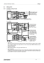
Positioning unit ready.
M code signal
(2-digit BCD).
M code ON signal.
M code OFF comand.
(The auxiliary unit operation
is completed.)
Subtask start
Subtask stop
Subtask single-step / cyclic
Subtask error
These operation inputs
vary depending on
parameter settings.
Mechanical system
Forward rotation
limit
Reverse rotation
limit
Near-point DOG
Forward rotation pulse
are stopped in the
forward rotaion limit.
Reverse rotation pulse
are stopped in the
reverse rotaion limit.
FP (forward rotation pulse)
or PLS (pulse).
RP (reverse rotation pulse)
or SIGN (sign).
Absolute position detection
signal.
I/O is set by parameters.
Zero point signal.
Clear signal. Generated
when machine zero return
is completed.
Servo ready.
Pulse input is valid.
Servo end.
Positioning is completed.
Drives forward /
reverse rotation
1 pulse per specified
rotation angle of the
motor.
When the HR-H servo
motor is connected.
Clears the deviation
counter.
Output when the power
supply of the drive unit
is turned ON and the
status is normal.
Output when the devia-
tion counter indicates a
value less than the spe-
cified value.
Stepping
motor
Servo motor
Drive unit
X axis
Y axis
Summary of Contents for FX2N-10GM
Page 1: ...HARDWARE PROGRAMMING MANUAL FX2N 10GM FX2N 20GM ...
Page 4: ...FX Series Positioning Controllers ii ...
Page 6: ...FX Series Positioning Controllers iv ...
Page 46: ...FX Series Positioning Controllers Introduction 1 1 34 MEMO ...
Page 76: ...FX Series Positioning Controllers Wiring 3 3 24 MEMO ...
Page 222: ...FX Series Positioning Controllers Operation Maintenance and Inspection 8 8 18 MEMO ...
Page 256: ...FX Series Positioning Controllers Program Examples 9 9 34 MEMO ...

