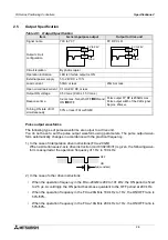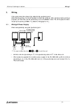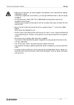
FX Series Positioning Controllers
Specifications 2
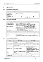
2-3
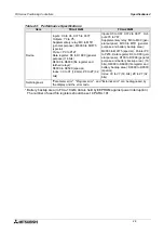
* Battery backup area (In FX
2N
-10GM, data is held by EEPROM against power interruption.)
The number of used file registers should be set in PARA. 101.
Device
Inputs: X0 to X3, X375 to X377
Outputs: Y0 to Y5,
Supplementary relay: M0 to M511
(general purpose), M9000 to M9175
(special)
Pointer: P0 to P127
Data register: D0 to D1999 (general
purpose) (16 bits)
D4000 to D6999 (file register and
latched relays)
*
D9000 to D9599 (special)
Index: V0 to V7 (16 bits), Z0 to Z7 (32
bits)
Inputs: X0 to X67, X372 to X377 Out-
puts:Y0 to Y67,
Supplementary relay: M0 to M99 (gen-
eral purpose), M100 to M511 (general
purpose and battery backup area)
*
,
M9000 to M9175 (special)
*
, Pointer:P0
to P255, Data register: D0 to D99 (gen-
eral purpose), D100 to D3999 (general
purpose and battery backup area)
*
(16
bits), D4000 to D6999 (file register and
battery backup area)
*
D9000 to D9599
(special)
Index: V0 to V7 (16 bits), Z0 to Z7 (32
bits)
Self-diagnosis
"Parameter error", "Program error", and "External error" can be diagnosed by
the display and the error code.
Table 2.3: Performance Specifications
Item
FX
2N
-10GM
FX
2N
-20GM
Summary of Contents for FX2N-10GM
Page 1: ...HARDWARE PROGRAMMING MANUAL FX2N 10GM FX2N 20GM ...
Page 4: ...FX Series Positioning Controllers ii ...
Page 6: ...FX Series Positioning Controllers iv ...
Page 46: ...FX Series Positioning Controllers Introduction 1 1 34 MEMO ...
Page 76: ...FX Series Positioning Controllers Wiring 3 3 24 MEMO ...
Page 222: ...FX Series Positioning Controllers Operation Maintenance and Inspection 8 8 18 MEMO ...
Page 256: ...FX Series Positioning Controllers Program Examples 9 9 34 MEMO ...

