FX Series Positioning Controllers
Program format 5
5-12
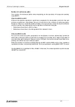
Operations of m codes during continuous paths
When m codes of the WITH mode are specified in continuous path interpolation instructions, a
series of continuous operations are performed even if the m code OFF command is not entered.
When a series of operations are completed and the m code OFF command is entered, the
machine proceeds to the next operation.
When different m codes are specified in each interpolation drive instruction as in the program
shown below, the m code outputs are switched one by one. Note that a new m code cannot be
read if the m code OFF command is not given before the switching point.
Program example
cod 01
(operand) m10;
cod 01
(operand) m11;
cod 01
(operand) m12;
(operand): Set the operands x, y, f, etc.
Other cautions and remarks
Incremental travel of interpolation control.
•
The incremental travel caused by one interpolation control instruction is restricted to 28 bits
when converted into pulses.
•
For example, when a travel of 1
µ
m per pulse is supposed, it corresponds to the incremental
travel of 268 m.
Stepping motor and continuous paths.
•
When a stepping motor is used to perform continuous path control, the motor may be out of
order depending on the motor characteristics.
Interpolation control and pulse output format.
•
In interpolation control, PARA. 11 (pulse output format) must be set to "0".
Remarks on circular interpolation.
•
During circular interpolation, the radius is constant and the pulses are distributed to the X
and Y axes.
Accordingly, if the ratio of the pulse rate and the feed rate (set to PARAs 1 and 2) is not
equivalent in the X and Y axes, a deformed arc will be obtained. In this case, adjust the
electronic gear of the servo amplifier to make the ratio equivalent in both the X and Y axes.
•
When an arc is small and the travel time from the start point to the end point is shorter than
the acceleration/deceleration time constant (set to PARA. 10), interpolation is impossible. In
this case, the locus of the travel from the start point to the end point becomes linear instead
of circular.
m10
m11
m12
m code ON
m code OFF
command
In the example above, a strobe
to read m11 is not obtained.
Summary of Contents for FX2N-10GM
Page 1: ...HARDWARE PROGRAMMING MANUAL FX2N 10GM FX2N 20GM ...
Page 4: ...FX Series Positioning Controllers ii ...
Page 6: ...FX Series Positioning Controllers iv ...
Page 46: ...FX Series Positioning Controllers Introduction 1 1 34 MEMO ...
Page 76: ...FX Series Positioning Controllers Wiring 3 3 24 MEMO ...
Page 222: ...FX Series Positioning Controllers Operation Maintenance and Inspection 8 8 18 MEMO ...
Page 256: ...FX Series Positioning Controllers Program Examples 9 9 34 MEMO ...


