FX Series Positioning Controllers
Parameters 4
4-27
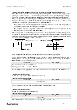
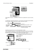
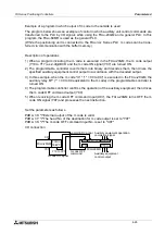
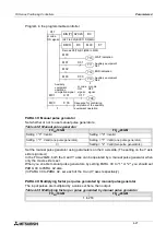
Program in the programmable controller
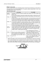
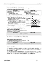
PARA. 39: Manual pulse generator
Set whether or not to use manual pulse generators.
Set the manual pulse generator using parameters on the X axis side. (The setting on the Y axis
side is ignored.)
In the FX
2N
-20GM, both the X and Y axes can be operated by a manual pulse generator when
only the X axis side is set.
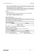
When you enable manual pulse generators by setting PARA. 39 to "1" or "2", you should set
PARA. 40 to PARA. 42 also.
(In PARA. 40 to PARA. 42, set each of the X and Y axes respectively.)
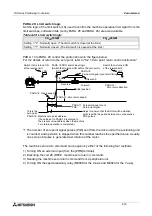
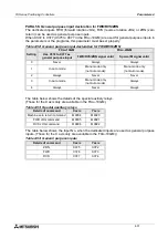
PARA. 40: Multiplying factor per pulse generated by manual pulse generator
The input pulses are multiplied by a value set here, then output.
Table 4.42: Manual pulse generator
FX
2N
-10GM
FX
2N
-20GM
Setting = "0" : Invalid
Setting = "0" : Invalid
Setting = "1" : Valid (one pulse generator).
Setting = "1" : Valid (one pulse generator).
Setting = "2" : Valid (two pulse generators).
Table 4.43: Multiplying factor per pulse generated by manual pulse generator
FX
2N
-10GM
FX
2N
-20GM
1 to 255
X17
BIN [P] K2X20
D 0
DECO
D 0
M 00
K 7
(X27 to X20)BCD D 0(BIN)
Decode D0(7bit) (M99 to M00)
M 00
Y10
M 01
Y11
X 31
M 02
Y12
M 03
Y13
X 33
X 31
Y00
X 17
Auxiliary
equipment
operation
completion signal
X 33
m code
ON signal
M01
M03
WAIT indication
END indication
Auxiliary equipment
No.1
Auxiliary equipment
No.2
m code
ON
signal
m code
OFF
signal
Sequence for confirming
completion of the auxiliary
equipment operation
→
~
~
→
Summary of Contents for FX2N-10GM
Page 1: ...HARDWARE PROGRAMMING MANUAL FX2N 10GM FX2N 20GM ...
Page 4: ...FX Series Positioning Controllers ii ...
Page 6: ...FX Series Positioning Controllers iv ...
Page 46: ...FX Series Positioning Controllers Introduction 1 1 34 MEMO ...
Page 76: ...FX Series Positioning Controllers Wiring 3 3 24 MEMO ...
Page 222: ...FX Series Positioning Controllers Operation Maintenance and Inspection 8 8 18 MEMO ...
Page 256: ...FX Series Positioning Controllers Program Examples 9 9 34 MEMO ...


