FX Series Positioning Controllers
Wiring 3
3-6
•
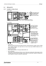
Input sensitivity
The input current of the positioning unit is 24V DC, 7 mA. However, in order to securely turn
on the positioning unit, the input current should be 4.5 mA or more. In order to securely turn
off the positioning unit, the input current should be 1.5 mA or less. Accordingly, if series
diodes or resistors are present in input contacts (which hinder complete ON) or if parallel
resistors or leak current is present in input contacts (which hinder complete OFF), you
should select input equipment with rigid care.
•
Selection of DC input equipment
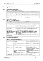
The input current of the positioning unit is 24V DC, 7 mA. Select small input equipment suit-
able to such weak current.
•
Install a safety circuit outside the PLC so that the entire system conservatively operates
even if an abnormality occurs in the external power supply or a failure occurs in the PLC.
If the safety circuit is installed inside the PLC, malfunction and erroneous output may
cause accidents.
1) Make sure to construct an emergency stop circuit, protection circuit, interlock circuit for
reverse operations such as normal rotation and reverse rotation and interlock circuit to
prevent damages of a machine for upper limit/lower limit, etc. outside the PLC.
2) When the CPU in the positioning unit detects an abnormality such as a watch dog timer
error by the self-diagnosis circuit, all outputs turn off. When an abnormality occurs in
the I/O control area which cannot be detected by the CPU in the PLC, output control
may be disabled.
Design external circuits and the structure so that the entire system conservatively oper-
ates in such cases.
3) When a failure occurs in a relay, transistor, TRIAC, etc. in the output unit, outputs may
keep ON or OFF.
For output signals which may lead to severe accidents, design external circuits and the
structure so that the entire system conservatively operates.
•
Make sure to shut down the power supplies of all phases on the outside before starting
installation or wiring.
If the power supplies are not shut down, you may get electrical shock or the unit may be
damaged.
•
All general purpose input of the GM unit are configured as SINK inputs.
•
Never touch any terminals while the power is supplied.
If you touch a terminal while the power is supplied, you may get electrical shock or the
unit may malfunction.
•
Turn off the power at first, then start cleaning or tighten terminals.
If you perform cleaning or tightening while the power is supplied, you may get electrical
shock.
Summary of Contents for FX2N-10GM
Page 1: ...HARDWARE PROGRAMMING MANUAL FX2N 10GM FX2N 20GM ...
Page 4: ...FX Series Positioning Controllers ii ...
Page 6: ...FX Series Positioning Controllers iv ...
Page 46: ...FX Series Positioning Controllers Introduction 1 1 34 MEMO ...
Page 76: ...FX Series Positioning Controllers Wiring 3 3 24 MEMO ...
Page 222: ...FX Series Positioning Controllers Operation Maintenance and Inspection 8 8 18 MEMO ...
Page 256: ...FX Series Positioning Controllers Program Examples 9 9 34 MEMO ...


