FX Series Positioning Controllers
Program Examples 9
9-5
9.2.4
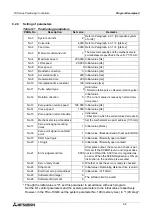
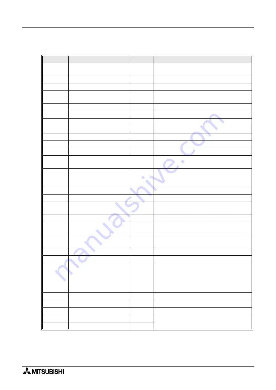
Setting of parameters
* Though the initial value is "0", set this parameter in accordance with each program.
Set the I/O control parameters and the system parameters to the initial values respectively.
However, in the FX
2N
-10GM, set the system parameter No. 100 (memory size) to "1 (4K step)".
Table 9.1: Positioning parameters
PARA. No.
Description
Set value
Remarks
No.0
System of units
2
Refer to Paragraph 4.3.1. [Composite system
of units]
No.1
Pulse rate
4,000 Refer to Paragraph 4.3.1
c
. [pls/rev]
No.2
Feed rate
5,000 Refer to Paragraph 4.3.1
d
. [pls/rev]
No.3
Minimum command unit
1
The movement quantity and the mechanical zero
point address are specified in the unit of "1/10 mm".
No.4
Maximum speed
200,000 Initial value [Hz]
No.5
JOG speed
20,000 Initial value [Hz]
No.6
Bias speed
0 Initial value [Hz]
No.7
Backlash correction
0 Initial value [
µ
m]
No.8
Acceleration time
200 Initial value [ms]
No.9
Deceleration time
200 Initial value [ms]
No.10
Interpolation time constant
100 Initial value [ms]
No.11
Pulse output type
0
Initial value
<Normal rotation pulse + Reverse rotation pulse>
No.12
Rotation direction
0
Initial value
<The current value increases by normal rota-
tion pulse.>
No.13
Zero position return speed
100,000 Initial value [Hz]
No.14
Creep speed
1,000 Initial value [Hz]
No.15
Zero position return direction
1
Initial value
<Direction in which the current value decreases>
No.16
Mechanical zero point address
* Set the mechanical zero point address [1/10 mm].
No.17
Zero point signal counting
times
1 Initial value [times]
No.18
Zero point signal count start
point
1 Initial value <Backward end of near point DOG>
No.19
DOG input logic
0 Initial value <Normally open contact>
No.20
LS logic
0 Initial value <Normally open contact>
No.21
Error judgement time
5,000
After pulse output, the servo end check is per-
formed. If the SVEND (servo end) signal does
not turn ON within 5,000 ms, it is regarded as
an error. When the SVEND signal turns ON, an
instruction in the next step is executed.
No.22
Servo ready check
0 Whether or not the servo is ready is checked.
No.23
Stop mode
1 Initial value <Remaining distance drive is valid.>
No.24
Electrical zero point address
0 Initial value <
×
1/10mm>
No.25
Software limit (large)
0
The software limit is invalid.
No.26
Software limit (small)
0
Summary of Contents for FX2N-10GM
Page 1: ...HARDWARE PROGRAMMING MANUAL FX2N 10GM FX2N 20GM ...
Page 4: ...FX Series Positioning Controllers ii ...
Page 6: ...FX Series Positioning Controllers iv ...
Page 46: ...FX Series Positioning Controllers Introduction 1 1 34 MEMO ...
Page 76: ...FX Series Positioning Controllers Wiring 3 3 24 MEMO ...
Page 222: ...FX Series Positioning Controllers Operation Maintenance and Inspection 8 8 18 MEMO ...
Page 256: ...FX Series Positioning Controllers Program Examples 9 9 34 MEMO ...


