FX Series Positioning Controllers
Communication with Programmable Controller 7
7-16
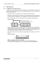
m code information
When a positioning instruction is driven, an m code is output.
At this time, the m code ON signal, the m code No. and the m code wait signal are written to
special auxiliary relays and special data registers (assigned to the X axis).
The m code OFF command is also given through a special auxiliary relay.
m code ON signal: M9051
m code No. (binary): D9003
m code wait signal: M9052
m code OFF command: M9003
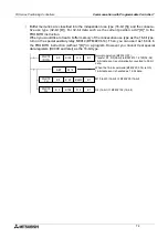
In the m code information, the AFTER mode (in which an m code is output after positioning is
completed) or the WITH mode (in which an m code is output while positioning is performed)
can be set for m code output.
Set value "0": No m code
Set value "1", "3" to "99": m code output in the AFTER mode
Set value "100" to "199": m code output in the WITH mode
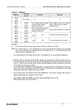
Positioning data list
The table below shows the list of information set for each command code. The items marked
with “
9
” are required to be set. When a value is entered for an item indicated as “Undefined”, it
is ignored.
The command code “72” indicates interrupt jog feed at two-step speed, and uses two entries
because two speeds are required to be set (Refer to the next page.).
*1: When the speed data is set to “0”, the command code (0) is ignored and the next entry is executed.
Table 7.6: Positioning data list
Command code Position data Speed data
m code
Remarks
0
9
9
*1
9
High-speed positioning. (DRV)
1
9
9
9
Multi speed operation. (LIN)
4
9
Undefined
9
Timer. (TIM)
9
Undefined
Undefined
9
Servo end check. (CHK)
28
Undefined
Undefined
9
Return to mechanical zero point. (DRVZ)
29
Undefined
Undefined
9
Setting of electrical zero point. (SETR)
30
Undefined
Undefined
9
Return to electrical zero point. (DRVR)
31
9
9
9
Interrupt stop (Remaining distance is
neglected). (INT)
71
9
9
9
Interrupt jog feed at one-step speed.
(One entries are used.) (SINT)
72
9
9
Undefined Interrupt jog feed at two-step speed.
(Two entries are used.) (DINT)
Undefined
9
9
73
9
Undefined
9
Travel compensation. (MOVC)
76
Undefined
Undefined
9
Cancel of compensation. (CANC)
90
Undefined
Undefined
9
Specification of absolute address. (ABS)
91
Undefined
Undefined
9
Specification of incremental address.
(INC)
92
9
Undefined
9
Change of present value. (SET)
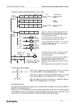
•
When "2" is set, the actual operation does not correspond to the END instruction.
(In the monitor display by a peripheral unit, however, "END" is displayed.)
When using the END instruction, add "2" at the top of the positioning information
as described above.
Summary of Contents for FX2N-10GM
Page 1: ...HARDWARE PROGRAMMING MANUAL FX2N 10GM FX2N 20GM ...
Page 4: ...FX Series Positioning Controllers ii ...
Page 6: ...FX Series Positioning Controllers iv ...
Page 46: ...FX Series Positioning Controllers Introduction 1 1 34 MEMO ...
Page 76: ...FX Series Positioning Controllers Wiring 3 3 24 MEMO ...
Page 222: ...FX Series Positioning Controllers Operation Maintenance and Inspection 8 8 18 MEMO ...
Page 256: ...FX Series Positioning Controllers Program Examples 9 9 34 MEMO ...

