FX Series Positioning Controllers
Parameters 4
4-21
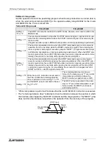
Operation caused by STOP command
*1 The timer stops. The machine is driven for the remaining time.
*2 The timer stops. The machine is not driven for the remaining time.
*3 The m code ON signal does not change by the stop command while the machine is waiting
for the m code.
Accordingly, when performing positioning after jump by the NEXT instruction, the m code
OFF command is required before the positioning start command.
*4 The m code No. changes into m02 (END). However, the m code ON signal does not change.
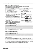
PARA. 24: Electrical zero point address
Set the absolute address for electrical zero return executed by the cod 30 (DRVR) instruction.
The unit is determined by PARA. 0 and PARA. 3. The address set by PARA. 24 represents an
absolute value.
PARA. 25: Software limit (upper)
When the present value becomes equal to or more than the set value, a limit error occurs.
Table 4.29: Operation caused by STOP command
Setting
FX
2N
-
10GM
FX
2N
-
20GM
Operation caused by STOP command
Remaining distance
Timer
m code
0, 4
9
9
The machine does not
stop
The machine does not
stop
Not changed
1
9
9
Valid
*1
Not changed
*3
2
9
9
Ignored
*2
Not changed
*3
3, 7
9
9
Ignored
*2
*4
5
9
Valid
*1
Not changed
*3
6
9
Ignored
*2
Not changed
*3
Table 4.30: Electrical zero point address
FX
2N
-10GM
FX
2N
-20GM
-999,999 to +999,999
Table 4.31: Software limit (upper)
FX
2N
-10GM
FX
2N
-20GM
Set a 32-bit value within the following range. -2,147,483,648 to +2,147,483,647
Summary of Contents for FX2N-10GM
Page 1: ...HARDWARE PROGRAMMING MANUAL FX2N 10GM FX2N 20GM ...
Page 4: ...FX Series Positioning Controllers ii ...
Page 6: ...FX Series Positioning Controllers iv ...
Page 46: ...FX Series Positioning Controllers Introduction 1 1 34 MEMO ...
Page 76: ...FX Series Positioning Controllers Wiring 3 3 24 MEMO ...
Page 222: ...FX Series Positioning Controllers Operation Maintenance and Inspection 8 8 18 MEMO ...
Page 256: ...FX Series Positioning Controllers Program Examples 9 9 34 MEMO ...


