FX Series Positioning Controllers
Introduction 1
1-15
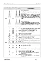
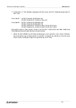
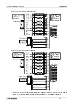
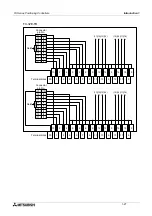
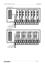
*1:In the table 1.2, "(X)" indicates assignment for the X axis, and "(Y)" indicates assignment for
the Y axis.
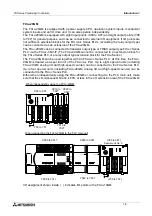
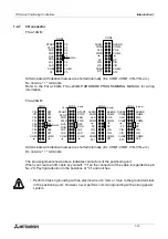
FX
2N
-10GM ...... CON1:Connector dedicated to I/O
CON2: Connector to connect a drive unit
FX
2N
-20GM ...... CON1: Connector dedicated to I/O
CON2: Connector dedicated to I/O
CON3: Connector to connect a drive unit (for the X axis)
CON4: Connector to connect a drive unit (for the Y axis)
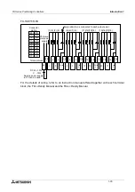
Description of two or more pin Nos. shown in the "Pin No." column such as COM1, COM2 and
VIN indicates that such pins are short-circuited inside.
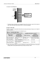
•
While the FX
2N
-20GM is performing simultaneous 2-axis operation, step mode command,
start command, stop command and m code OFF command are effective to the both axes
even if such a command is given to only either the X or Y axis.
Summary of Contents for FX2N-10GM
Page 1: ...HARDWARE PROGRAMMING MANUAL FX2N 10GM FX2N 20GM ...
Page 4: ...FX Series Positioning Controllers ii ...
Page 6: ...FX Series Positioning Controllers iv ...
Page 46: ...FX Series Positioning Controllers Introduction 1 1 34 MEMO ...
Page 76: ...FX Series Positioning Controllers Wiring 3 3 24 MEMO ...
Page 222: ...FX Series Positioning Controllers Operation Maintenance and Inspection 8 8 18 MEMO ...
Page 256: ...FX Series Positioning Controllers Program Examples 9 9 34 MEMO ...

