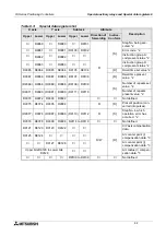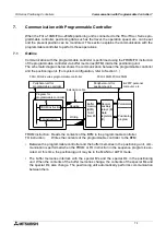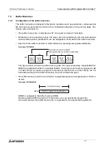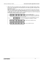
FX Series Positioning Controllers
Communication with Programmable Controller 7
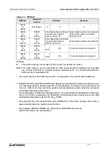
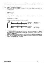
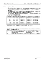
7-11
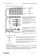
Sequence program example (Example for the X axis)
Positioning program example
Data reading timing
The data can be read without regard to the mode (AUTO or MANU) or the status (BUSY or
READY) of the positioning unit.
However, it is recommended to drive the auxiliary equipment when the m code ON signal is
turned ON as shown in the sequence program example above because the m code No. is only
read when an m code drive instruction is executed in the positioning program.
M8000
FROM
K 0
K 23
K4M200
K 1
RUN
monitor
Unit No.
FROM
K 0
K 3
D 0
K 1
TO
K 0
K 20
K4M300
K 1
DECO
D 0
M 00
K 7
M203
m code
ON
signal
M00
Y10
WAIT
indication
M01
Y11
Auxiliary
equipment
No.1
M02
Y12
END
indication
M03
Auxiliary
equipment
No.2
X31
M203
Auxiliary equipment
operation
completion signal
m code
ON signal
M303
m code
OFF signal
X33
Sequence for confirming
completion of the auxiliary
equipment operation.
X31
X33
M9063 to M9048
(M9051)
M 215 to M 200
(M 203)
D9003
(BFM #3)
D 0
M 315 to M 300
(M 303)
M9015 to M9000
(M9003)
M03
M01
Y13
When an m code is executed in the positioning unit,
D9003 (m code No., 0 to 99) and M9051 (m code
ON signal) are set and transmitted to D0 and M203
in the programmable controller.
The programmable controller decodes them, and
turns ON the specified auxiliary drive output.
In this example, when the m code m** (** = 00 to 99)
is executed, the auxiliary relay M** is turned ON in
the programmable controller.
The programmable controller confirms the operation
of the auxiliary equipment, then drives M303 (m
code OFF command).
When receiving the m code OFF command (M303 in
the programmable controller
→
M9003 in the
positioning unit), the positioning unit turns OFF
M9051 (m code ON signal) and proceeds to the next
instruction.
In the programmable controller, M203 is turned OFF.
·
·
·
·
·
Number
of points
Programmable
controller
BFM #
→
→
→
→
→
Positioning unit
PLC
cod 00 (DRV) x1000 m01
m03;
m00; (WAIT)
• This is an m code drive command in WITH mode. The m code
01 is saved in BFM. In the example above, Y11 is driven.
• This is an m code drive command in AFTER mode. The m code
03 is saved in BFM. In the example above, Y13 is driven.
• When the WAIT instruction is executed, m code 00 is saved in
BFM. In the example above, Y10 is driven.
Summary of Contents for FX2N-10GM
Page 1: ...HARDWARE PROGRAMMING MANUAL FX2N 10GM FX2N 20GM ...
Page 4: ...FX Series Positioning Controllers ii ...
Page 6: ...FX Series Positioning Controllers iv ...
Page 46: ...FX Series Positioning Controllers Introduction 1 1 34 MEMO ...
Page 76: ...FX Series Positioning Controllers Wiring 3 3 24 MEMO ...
Page 222: ...FX Series Positioning Controllers Operation Maintenance and Inspection 8 8 18 MEMO ...
Page 256: ...FX Series Positioning Controllers Program Examples 9 9 34 MEMO ...

