FX Series Positioning Controllers
Program format 5
5-61
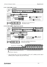
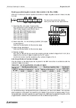
Reading a positive/negative numeric (Not available in the FX
2N
-10GM.)
When K17 to K24 are used to specify the number of digits, negative numeric values can also
be read.
1) Head input No. (Occupies 5 input points.)
The connections in this example are as follows.
X00: Positive/negative specification input.
When the X00 is ON:Negative value.
When the X00 is OFF:Positive value
X01: Terminal 1 of DSW
X02: Terminal 2 of DSW
X03: Terminal 4 of DSW
X04: Terminal 8 of DSW
2) Head output No. for time-sharing operation (Occupies
4 output points.)
Same as the description on the previous page.
3) Data storage destination
Same as the description on the previous page.
4) Number of digits
K17 (H11) to K24 (H18) are used in accordance with the number of digits from 1 to 8 (16 is
added to the number of digits to determine the "K" value.).
A 32-bit instruction must be used when the number of digits is 5 to 8.
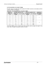
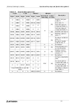
List of specification of number of digits
The I/Os shown in the table below are required for the EXT instruction in accordance with the
number of digits to be read.
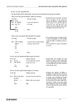
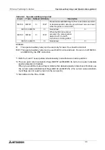
To read DSW settings, the digit-switching time (Initial value: 20 msec) set to PARA. 33 is required.
When a DSW is connected to the positioning unit, PARA. 33 can be set to approximately 7 msec.
If programmable controller outputs are used instead of a DSW take the digit-switching time of the
programmable controller into consideration and set a sufficient length of time.
Table 5.18: List of specification of number of digits
Number of
digits to
be read
Reading a positive value.
Reading a negative value.
Number of
data regis-
ters occu-
pied
Number of
inputs
Number of
outputs
"n" set
value
Number of
inputs
Number of
outputs
"n" set
value
1
4
1
K1
5
1
K17
1
2
2
K2
2
K18
3
3
K3
3
K19
4
4
K4
4
K20
5
5
K5
5
K21
6
6
K6
6
K22
2
7
7
K7
7
K23
8
8
K8
8
K24
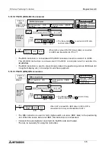
FNC 72
EXT
X00
Y00
D 0
K20
M 0
S·
D1·
D2·
n
This instruction performs time-sharing
reading of the data from the digital switches.
(1)
(2)
(3)
(4)
COM1
Extension block
Negative
/ positive
X04 X03 X02 X01 X00
8 4 2 1
1
4
2
3
Y03 Y02 Y01 Y00
8 4 2 1
C C C C
8 4 2 1 8 4 2 1 8 4 2 1
Summary of Contents for FX2N-10GM
Page 1: ...HARDWARE PROGRAMMING MANUAL FX2N 10GM FX2N 20GM ...
Page 4: ...FX Series Positioning Controllers ii ...
Page 6: ...FX Series Positioning Controllers iv ...
Page 46: ...FX Series Positioning Controllers Introduction 1 1 34 MEMO ...
Page 76: ...FX Series Positioning Controllers Wiring 3 3 24 MEMO ...
Page 222: ...FX Series Positioning Controllers Operation Maintenance and Inspection 8 8 18 MEMO ...
Page 256: ...FX Series Positioning Controllers Program Examples 9 9 34 MEMO ...


