FX Series Positioning Controllers
Communication with Programmable Controller 7
7-9
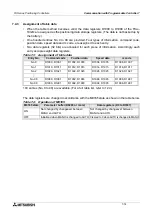
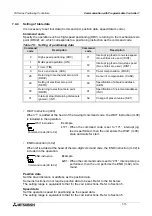
7.3.4
Setting the travel and the operation speed
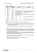
Set the positioning data such as the travel and operation speed from the programmable controller.
Buffer memory No.
#100 to #1999:FX
2N
-10GM
#100 to #6999:FX
2N
-20GM
These buffer memories are always handled as 32-bit data.
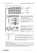
Refer to the positioning program example shown below.
Program example
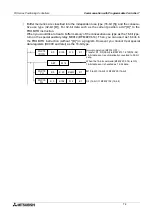
Write the set values in the D51, the D50 and the D100 to the BFM.
By turning ON special auxiliary relay M9014 (BFM #20, b14), 32-bit buffer memories are
treated as separate 16-bit types. This allows the TO instruction (without D ) to send 16-bit
data to each BFM separately. (Refer to Section 7.2.1.)
Positioning program example
In the positioning program, the travel, the operation speed, etc. are specified indirectly (Refer
to Section 5.5.).
Only travel and speed are shown in this example. In addition, all the devices such as the
radius, the center point, etc. that can be specified indirectly can be set from the programmable
controller.
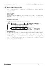
Data change timing
The data can be written to the buffer memories without regard to the mode (AUTO or MANU)
or the status (BUSY or READY) of the positioning unit. However, because the positioning unit
reads the travel and the speed set when the program is executed (when the cod instruction is
executed in the example above), the set data must be written to the buffer memories before the
instruction is executed. The data written while or after the instruction is executed becomes
valid when the instruction is executed next time.
FNC79
[D]TO
K 0
K100
D50
Drive
input
K1
Special
unit No.0
BFM
Programmable
controller
transfer source
Number of
transgers
Programmable
controller
D51, D50
Positioning unit
No.0 BFM #101,
#100(D101, D100)
FNC79
TO
K 0
K200
D100
K1
Programmable
controller
D100
Positioning unit
No.0 BFM
#200(D200)
Drive
input
→
→
cod00(DRV)
x DD100;
The travel is specified by D101 and D100 (32-bit data). ("DD"
specifies 32 bits.) The speed is specified as "fDDOOO".
Data register No.
cod00(DRV)
x D0;
The travel is specified by D0 (16-bit data). The speed is
specified as fDOOO.
Data register No.
Data register No.
Summary of Contents for FX2N-10GM
Page 1: ...HARDWARE PROGRAMMING MANUAL FX2N 10GM FX2N 20GM ...
Page 4: ...FX Series Positioning Controllers ii ...
Page 6: ...FX Series Positioning Controllers iv ...
Page 46: ...FX Series Positioning Controllers Introduction 1 1 34 MEMO ...
Page 76: ...FX Series Positioning Controllers Wiring 3 3 24 MEMO ...
Page 222: ...FX Series Positioning Controllers Operation Maintenance and Inspection 8 8 18 MEMO ...
Page 256: ...FX Series Positioning Controllers Program Examples 9 9 34 MEMO ...

