FX Series Positioning Controllers
Introduction 1
1-9
FX
2N
-20GM
The FX
2N
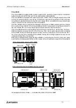
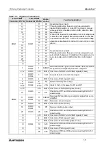
-20GM is equipped with a power supply, CPU, operation system inputs, mechanical
system inputs and an I/O drive unit. It can also operate independently.
The FX
2N
-20GM is equipped with eight input points (X00 to X07) and eight output points (Y00
to Y07) for general purpose, and can be connected to external I/O equipment. If I/O points are
not sufficient, extension blocks for the FX
2N
/
2NC
Series PLC’s (excluding the relay output type)
can be connected as an extension of the FX
2N
-20GM.
The FX
2N
-20GM can be connected to transistor output type or TRIAC output type FX
2NC
Series
PLC via the FX
2NC
-CNV-IF. (The FX
2N
-20GM cannot be connected to an extension block for
the FX
0N
Series PLC or a relay output type extension block for the FX
2N
Series.)
The FX
2N
-20GM can be used together with an FX
2N
/
2NC
Series PLC. At this time, the FX
2N
-
20GM is treated as a special unit of the FX
2N
/
2NC
PLC. Up to eight special units (including
FX
2N
-20GM, analog I/O and high-speed counter) can be connected to the FX
2N
Series PLC.
Up to four special units (including FX
2N
-20GM, analog I/O and high-speed counter) can be
connected to the FX
2NC
Series PLC.
Either when independently using the FX
2N
-20GM or connecting it to the PLC main unit, make
sure that the simultaneous ON ratio is 50% or less in the I/O extension area of the FX
2N
-20GM.
I/O assignment shown inside ( ) indicates I/O points in the FX
2N
-10GM.
X010 to
X027
X00 to X07
Y00 to Y07
Y010 to
Y027
SVRDY-X
LSR
LSF
CLR
RP
FP
PG0
SVEND
SVRDY Y
Y6
Y7
X0
X2
X3
X4
X5
X6
Y0
Y1
Y2
Y3
X1
Y5
X7
Y4
AUTO
MANU
POWER
ERROR-y
CPU-E
PG0
FP
RP
CLR
SVEND
LSR
LSF
DOG
RVS
FWD
ZRN
STOP
START Y
6
7
X0
2
3
X4
5
6
Y0
1
2
3
1
5
7
Y4
BATT
READY-x
ERROR-x
READY-y
DOG
RVS
START X
STOP
ZRN
FWD
FX -20GM
2N
X030 to
X047
When independently using the FX
2N
-20GM
X0
X2
X3
X4
X5
X6
X1
X7
POWER
X0
X2
X3
X4
X5
X6
X1
X7
Y0
Y2
Y3
Y4
Y5
Y6
Y1
Y7
POWER
Y0
Y2
Y3
Y4
Y5
Y6
Y1
Y7
X0
X2
X3
X4
X5
X6
X1
X7
POWER
X0
X2
X3
X4
X5
X6
X1
X7
1
IN 0
7
2
3
4
5
6
POWER
1
IN 0
7
2
3
4
5
6
7
2
4
5
6
1
3
0
16
11
15
14
17
10
12 13
14
17
15
10
12 13
7
2
4
5
6
1
3
0
16
11
OUT
IN
L
X13
X15
X10
X14
X16
24+
N
COM
X4
X7
Y4
Y5
Y6
COM3
Y10
Y11
Y12
Y13
Y1
Y2
Y3
Y14
Y15
X3
X2
X1
POWER
BATT.V
RUN
CPU.E
PROG.E
1
OUT 0
7
2
3
4
5
6
POWER
1
OUT 0
7
2
3
4
5
6
X000 to X017
X020 to X027
(X00 to X07)
Special unit No. 0
Y000 to Y017
(Y00 to Y07)
Y020 to Y027
SVRDY-X
LSR
LSF
CLR
RP
FP
PG0
SVEND
SVRDY Y
Y6
Y7
X0
X2
X3
X4
X5
X6
Y0
Y1
Y2
Y3
X1
Y5
X7
Y4
AUTO
MANU
POWER
ERROR-y
CPU-E
PG0
FP
RP
CLR
SVEND
LSR
LSF
DOG
RVS
FWD
ZRN
STOP
START Y
6
7
X0
2
3
X4
5
6
Y0
1
2
3
1
5
7
Y4
BATT
READY-x
ERROR-x
READY-y
DOG
RVS
START X
STOP
ZRN
FWD
FX -20GM
2N
When connecting the FX
2N
-20GM to the PLC main unit
Summary of Contents for FX2N-10GM
Page 1: ...HARDWARE PROGRAMMING MANUAL FX2N 10GM FX2N 20GM ...
Page 4: ...FX Series Positioning Controllers ii ...
Page 6: ...FX Series Positioning Controllers iv ...
Page 46: ...FX Series Positioning Controllers Introduction 1 1 34 MEMO ...
Page 76: ...FX Series Positioning Controllers Wiring 3 3 24 MEMO ...
Page 222: ...FX Series Positioning Controllers Operation Maintenance and Inspection 8 8 18 MEMO ...
Page 256: ...FX Series Positioning Controllers Program Examples 9 9 34 MEMO ...

