Troubleshooting 10
10-1
10.
Troubleshooting
When an error has occurred first, check whether or not the supply voltage is correct and
whether or not loose terminal screws or imperfect contact of connectors can be found on the
positioning unit or the I/O units.
10.1
Troubleshooting using LEDs
The error condition can be found by checking the status of the various LEDs provided on the
positioning unit.
LED names
Power indication
"POWER" LED DISPLAY
•
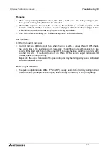
If the POWER LED is not lit when the power is turned ON, disconnect the various I/O units.
If the POWER LED is lit correctly with the units disconnected,
1) The 24V DC service power supply exceeds its capacity (with the FX
2N
-20GM).
•
With the FX
2N
-20GM, a fuse inside the unit may be blown out when conductive objects have
entered or another error has occurred. In this case, replacement of the fuse is not sufficient.
Contact the Mitsubishi Service Center.
Ready status
"READY" LED OFF
•
The READY LED is lit without regard to the mode (MANU or AUTO) while the positioning
unit is ready for accepting various operation commands (Refer to Section 8.1.7.).
If the READY LED is OFF,
1) While positioning is performed (pulses are being output).
→
Enter the stop command or change over the mode from AUTO to MANU to stop the
operation and light this LED.
2) When an error has occurred.
→
Check the reason for the error, and remove the cause.
ZRN
FWD
Y4
Y5
RP
STOP
FP
X2
X3
Y0
Y1
Y2
START
Y3
CLR
AUTO
MANU
POWER
READY
ERROR
CPU-E
X0
RVS
DOG
LSF
LSR
X1
PGO
SVRDY
SVEND
FX -10GM
2N
POWER
READY
ERROR
CPU-E
SVRDY-X
LSR
LSF
CLR
RP
FP
PG0
SVEND
SVRDY Y
Y6
Y7
X0
X2
X3
X4
X5
X6
Y0
Y1
Y2
Y3
X1
Y5
X7
Y4
AUTO
MANU
POWER
ERROR-y
CPU-E
PG0
FP
RP
CLR
SVEND
LSR
LSF
DOG
RVS
FWD
ZRN
STOP
START Y
6
7
X0
2
3
X4
5
6
Y0
1
2
3
1
5
7
Y4
BATT
READY-x
ERROR-x
READY-y
DOG
RVS
START X
STOP
ZRN
FWD
FX -20GM
2N
READY-y
ERROR-x
READY-x
BATT
CPU-E
ERROR-y
POWER
MANU
AUTO
Power/status
Indicator LEDs
FX
2N
-10GM
FX
2N
-20GM
Power/status
Indicator LEDs
I/O
Indicator
LEDs
I/O
Indicator
LEDs
FX Series Positioning Controllers
Summary of Contents for FX2N-10GM
Page 1: ...HARDWARE PROGRAMMING MANUAL FX2N 10GM FX2N 20GM ...
Page 4: ...FX Series Positioning Controllers ii ...
Page 6: ...FX Series Positioning Controllers iv ...
Page 46: ...FX Series Positioning Controllers Introduction 1 1 34 MEMO ...
Page 76: ...FX Series Positioning Controllers Wiring 3 3 24 MEMO ...
Page 222: ...FX Series Positioning Controllers Operation Maintenance and Inspection 8 8 18 MEMO ...
Page 256: ...FX Series Positioning Controllers Program Examples 9 9 34 MEMO ...


