FX Series Positioning Controllers
Wiring 3
3-20
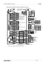
When the FX
2N
-20GM is connected to a MR-C servo motor.
CON4
19
11
12
17
18
9
1
2
COM3/7
Y01
Y00
COM1
X07
X06
X01
X00
COM1
18
x axis
11
12
13
14
15
16
17
LSR
LSF
DOG
RVS
FWD
ZRN
STOP
START
COM1
Y02
3
Y03
4
Y06
7
Max
50mA
CON1
Y07
8
11
1
COM2/6
2
COM2/6
12
SVEND
11
COM4/8
14
PGO
13
VIN
7,8,
17,18
5
FP
6
COM5/9
9,19
RP
16
15
CLR
3
4
y axis
SVRDY
SD
V+
V+
OPC
V24
PP
SG
NP
CN1
CR
PF
OP
CN1
CN1
SG
13
7
9
20
19
4
1
1
3
5
12 SG
14 LSN
15 LSP
17 SON
12 SG
20 V24
CN1
2
ALM
CN1
PG
C P
L1
L2
E
W
V
U
W
V
U
CN2
NFB
MC
M
19
ALM 2
CN1
9
1
2
3
4
5
6
7
8
y axis
X02
13
X03
14
X04
15
X05
16
5
Y04
6
Y05
2
12
11
14
13
7,8,
17,18
5
9,19
6
16
15
3
4
1
CON3
x axis
*1
*1
DC24V
5 to 24V
ST2/4
ST1/3
10
20
10
20
24- 24+
Automatic
Start
Stop
Zero return
Manual forward rotation
Manual reverse rotation
Near-point signal
Forward rotation limit
Reverse rotation limit
5 to 24V
General purpose inputs
Y axis X axis
The EN and x/y
entries ars examples.
31
ZRN
X372
FWD
X373
X374
A
72 - x
B
72 - x
71 - y
RVS
Manual
Table: Assignment of X00 to X07.
EN
Automatic
X375
X376
X377
72 - y
72 - y
71 - x
x / y
x - A
x - B
y - A
y - B
x - EN
y - EN
Manual pulse
generator
Interrupt
input
3.3k
W
3.3k
W
3.3k
W
3.3k
W
3.3k
W
2k
W
150
W
Power supply
MC-C A
MC-C A1
:Single phase,
200V AC
:Single phase,
100V AC
Regenerative option
HA-FE
Servo motor
Cable length: 2m max.
The optional cable
(E-GMC-200CAB) is provided
for the positioning unit.
MR-C A (1) servo amplifier.
*1
*2
Fault
24V DC
power supply
0.2A or more
Servo ON
Forward rotation
limit *2
Reverse rotation
limit *2
Connect so that
MC is turned
OFF by alarm or
emergency stop.
Do the ground
wiring with
of the servo
amplifier.
: CN1 and CN2 have the same shape.
If they are confused in connection,
fault may occur.
: When the factory is shipped, LSP and
LSN are setting of normally open.
Wiring can be omitted.
5
General purpose outputs
Summary of Contents for FX2N-10GM
Page 1: ...HARDWARE PROGRAMMING MANUAL FX2N 10GM FX2N 20GM ...
Page 4: ...FX Series Positioning Controllers ii ...
Page 6: ...FX Series Positioning Controllers iv ...
Page 46: ...FX Series Positioning Controllers Introduction 1 1 34 MEMO ...
Page 76: ...FX Series Positioning Controllers Wiring 3 3 24 MEMO ...
Page 222: ...FX Series Positioning Controllers Operation Maintenance and Inspection 8 8 18 MEMO ...
Page 256: ...FX Series Positioning Controllers Program Examples 9 9 34 MEMO ...

