FX Series Positioning Controllers
Wiring 3
3-8
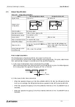
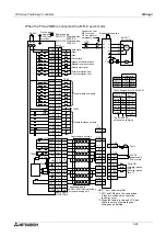
3.2.2
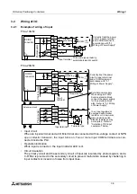
Output connection example
•
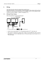
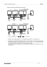
In the positioning unit, use COM1 for both input and output (common I/O).
•
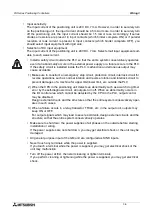
For pairs of inputs such as forward/reverse rotation contacts which would pose a hazard
if turned ON simultaneously, provide external interlocks, in addition to interlocks in the
program inside the positioning unit, to ensure that they cannot be turned ON simulta-
neously.
•
Make sure to shut down the power supplies of all phases on the outside before starting
installation or wiring.
If the power supplies are not shut down, you may get electrical shock or the unit may be
damaged.
•
Never touch any terminals while the power is supplied.
If you touch a terminal while the power is supplied, you may get electrical shock or the
unit may malfunction.
•
Turn off the power at first, then start cleaning or tighten terminals.
If you perform cleaning or tightening while the power is supplied, you may get electrical
shock.
Y004
Y007
Y006
Y005
COM1
Y003
Y002
Y001
Y000
MC1
MC1
MC
+
0.5A
0.5A
0.5A
Interlock
MC1
MC2
External power supply
5 to 24V DC
A fuse is not provided
in the output circuit
Handle the vacant
terminal correctly
following "Cautions on wiring".
Provide a 0.5A fuse for
each group of 8 points
to prevent meltdown of
the wiring on the PC
Board caused by load
shortcircuit, etc.
Example of FX
2N
-20GM
output circuit
´
Forward
rotation
limit
Output element
Reverse
rotation
limit
Forward
rotation
Reverse
rotation
Summary of Contents for FX2N-10GM
Page 1: ...HARDWARE PROGRAMMING MANUAL FX2N 10GM FX2N 20GM ...
Page 4: ...FX Series Positioning Controllers ii ...
Page 6: ...FX Series Positioning Controllers iv ...
Page 46: ...FX Series Positioning Controllers Introduction 1 1 34 MEMO ...
Page 76: ...FX Series Positioning Controllers Wiring 3 3 24 MEMO ...
Page 222: ...FX Series Positioning Controllers Operation Maintenance and Inspection 8 8 18 MEMO ...
Page 256: ...FX Series Positioning Controllers Program Examples 9 9 34 MEMO ...

