FX Series Positioning Controllers
Introduction 1
1-14
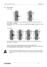
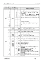
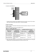
CON1
11
CON1
11
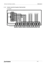
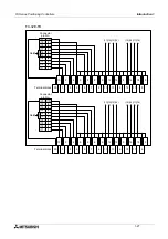
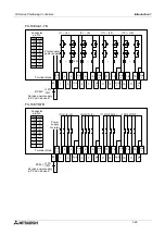
X0
General-purpose inputs
Through parameters, these pins can be assigned to
inputs of digital switch, m code OFF command, manual
pulse generator, absolute position (ABS) detection data,
step mode, etc.
When STEP input set by a parameter turns on, step mode
is selected, and program execution proceeds to next line
in accordance with "OFF
→
ON" of start command. Step
operation is disabled until command in current line is com-
pleted.
12
12
X1
13
13
X2
14
14
X3
15
X4
16
X5
17
X6
18
X7
10
5
Y1
General-purpose outputs
Through parameters, these pins can be assigned to out-
puts of digit changeover of digital switch, ready signal, m
code, absolute position (ABS) detection control signal,
etc.
15
1
Y2
16
2
Y3
17
3
Y4
18
4
Y5
20
6
Y6
7
Y7
8
Y8
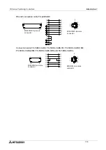
CON2
1
CON3
CON4
1
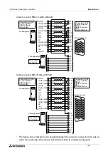
SVRDY
Receives READY signal (which indicates that preparation
for operation is completed) from servo amplifier.
2,12
CON3
2,12
COM2 Common of SVRDY and SVEND signals (X axis)
3
CON3
CON4
3
CLR
Outputs deviation counter clear signal.
4
CON3
4
COM3 Common of CLR signal (X axis)
6
CON3
CON4
6
FP
Normal rotation pulse output
7,8,
17,18
7,8,
17,18
VIN
Input (5 V, 24 V) for power for FP and RP
9,19
CON3
9,19
COM5 Common of FP and RP signals (X axis)
10
10
ST1
Short-circuit ST1 and ST2 when connecting PG0 to 5 V
power supply.
11
CON3
CON4
11
SVEND
Receives INP (positioning completion) signal from servo
amplifier.
13
13
PG0
Receives zero point signal.
14
CON3
14
COM4 Common of PG0 (X axis)
16
CON3
CON4
16
RP
Reverse rotation pulse output
20
CON3
20
ST2
Short-circuit ST1 and ST2 when connecting PG0 to 5 V
power supply.
CON4
2,12
COM6 Common of SVRDY and SVEND signals (Y axis)
4
COM7 Common of CLR signal (Y axis)
9
COM9 Common of FP and RP signals (Y axis)
10
ST3
Short-circuit ST3 and ST4 when connecting PG0 to 5 V
power supply.
14
COM8 Common of PG0 signal (Y axis)
20
ST4
Short-circuit ST3 and ST4 when connecting PG0 to 5 V
power supply.
Table 1.2: Signals in connectors
FX
2N
-10GM
FX
2N
-20GM
Abbre-
viation
Function/application
Connector Pin No. Connector Pin No.
Summary of Contents for FX2N-10GM
Page 1: ...HARDWARE PROGRAMMING MANUAL FX2N 10GM FX2N 20GM ...
Page 4: ...FX Series Positioning Controllers ii ...
Page 6: ...FX Series Positioning Controllers iv ...
Page 46: ...FX Series Positioning Controllers Introduction 1 1 34 MEMO ...
Page 76: ...FX Series Positioning Controllers Wiring 3 3 24 MEMO ...
Page 222: ...FX Series Positioning Controllers Operation Maintenance and Inspection 8 8 18 MEMO ...
Page 256: ...FX Series Positioning Controllers Program Examples 9 9 34 MEMO ...

