238
7 CONTROL SUB FUNCTIONS
7.4 Function to Limit Control
Precautions for the software stroke limit check
• To execute Software stroke limit function properly, the machine OPR must be performed beforehand.
• During the interpolation control, the stroke limit check is performed for every current value of both the reference axis and
interpolation axes. All the axes do not start if an error occurs even if an error occurs only in one axis.
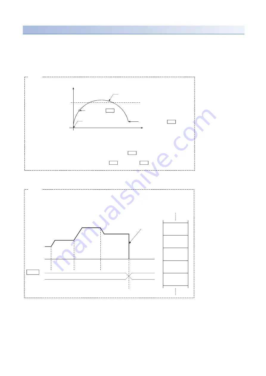
• During the circular interpolation control, [Pr.12] Software stroke limit upper limit value or [Pr.13] Software stroke limit lower
limit value may be exceeded. In this case, the machine does not decelerate and stop even if the stroke limit is exceeded.
Always install limit switches externally if the stroke limit may be potentially exceeded.
• If an error is detected during the continuous path control, the operation stops at the completion of the execution of the
positioning data right before the positioning data having the error.
• When the simultaneous start is performed, the stroke limit check is performed for every current value of the axes to be
started simultaneously. All the axes do not start if an error occurs even if an error occurs only in one axis.
Arc address ( Da.7 )
End point address ( Da.6 )
Axis 1
Axis 1 stroke limit
Deceleration stop not carried out
Start point address
*
Axis 2
Example
The software stroke limit check is carried out for the following addresses during circular
interpolation control. (Note that the limit check for Da.7 Arc address is carried out only
for the circular interpolation control with sub point specified.)
Current value/end point address ( Da.6 )/Arc address ( Da.7 )
Md. 26
No.11
No.10
No.12
No.13
No.10
P11
No.11
P11
No.12
P11
No.13
P11
No.14
P01
Axis
operation
status
Immediate stop
at error detection
Position control
Error
Positioning data
If the positioning address of positioning data No.13 is outside the software stroke limit range,
the operation immediately stops when the execution of positioning data No.12 is completed.
⋅
Example
Summary of Contents for MELSEC iQ-R RD75P4
Page 1: ...MELSEC iQ R Positioning Module User s Manual Application RD75P2 RD75P4 RD75D2 RD75D4 ...
Page 2: ......
Page 13: ...11 MEMO ...
Page 19: ...17 CONTENTS INDEX 588 REVISIONS 592 WARRANTY 593 TRADEMARKS 594 ...
Page 498: ...496 13 PROGRAMMING 13 2 List of Labels Used ...
Page 503: ...13 PROGRAMMING 13 4 Program Example 501 13 ...
Page 514: ...512 13 PROGRAMMING 13 4 Program Example Restart program Parameter data initialization program ...
Page 515: ...13 PROGRAMMING 13 4 Program Example 513 13 Flash ROM write program Error reset program ...
Page 516: ...514 13 PROGRAMMING 13 4 Program Example Stop program ...
Page 565: ...APPENDICES Appendix 4 Operation Examples of When the Remote Head Module Is Mounted 563 A ...
Page 597: ......


