5-10 Image Optimization
During M mode imaging, you can switch between B and M menu from the menu title.
During M Mode scanning, frequency and acoustic power of the transducer are
synchronous with that of B Mode.
Adjustment of the depth or TGC to the B Mode image will lead to corresponding changes
in M Mode image.
5.5.3
M Mode Image Optimization
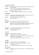
Gain
Description
To adjust the gain of M mode image. The real-time gain value is displayed in the
image parameter area in the upper left corner of the screen.
Operation
Rotate the <Gain/ iTouch> knob clockwise to increase the gain, and anti-
clockwise to decrease.
The adjusting range is 0-100.
Effects
Increasing the gain will brighten the image and you can see more received
signals. However, noise may also be increased.
Depth
Description
This function is used to adjust the display depth of sampling, the real-time
value of which is displayed on the image parameter area in the upper left
corner of the screen.
Operation
Use the <Depth/Zoom> knob to adjust the depth.
The adjustable depth values vary depending upon the probe types.
Effects
Increase the depth to see tissue in deeper locations, while decrease the depth
to see tissue in shallower locations.
Impacts
Depth increase will cause a decrease in the frame rate.
Frequency
Description
This function is used to select the operating frequency of the current probe,
the real-time value of which is displayed in the image parameter area in the
upper left corner of the screen, where “F” represents B mode frequency, and
“FH” represents harmonic frequency.
Operation
Adjust it through [Frequency] on the image menu, wherein
“H” means the
harmonic frequency.
Values of frequency vary depending upon the probe types. Select the
frequency according to the detection depth and current tissue characteristics.
Effects
The higher the frequency the better the near field resolution but the worse the
force of penetration.
Harmonic imaging enhances near field resolution and reduces low-frequency
and large amplitude noise, so as to improve small parts imaging.
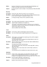
A. power
Description
Refers to the power of ultrasonic wave transmitted by the probe, the real-time
value of which is displayed in the image parameter area in the upper left corner
of the screen.
Summary of Contents for DP-50 Exp Vet
Page 2: ......
Page 34: ...2 6 System Overview 2 6 Introduction of Each Unit Right View Left View...
Page 42: ......
Page 68: ......
Page 128: ......
Page 148: ......
Page 166: ...10 18 DICOM For details on tast manager see 9 6 Animal Task Manager...
Page 180: ......
Page 220: ......
Page 224: ......
Page 236: ......
Page 242: ......
Page 248: ......
Page 342: ...D 2 Printer Adapter Type Model SONY X898MD...
Page 343: ...P N 046 017713 02 1 0...


