background image

www.hygiena.com

20

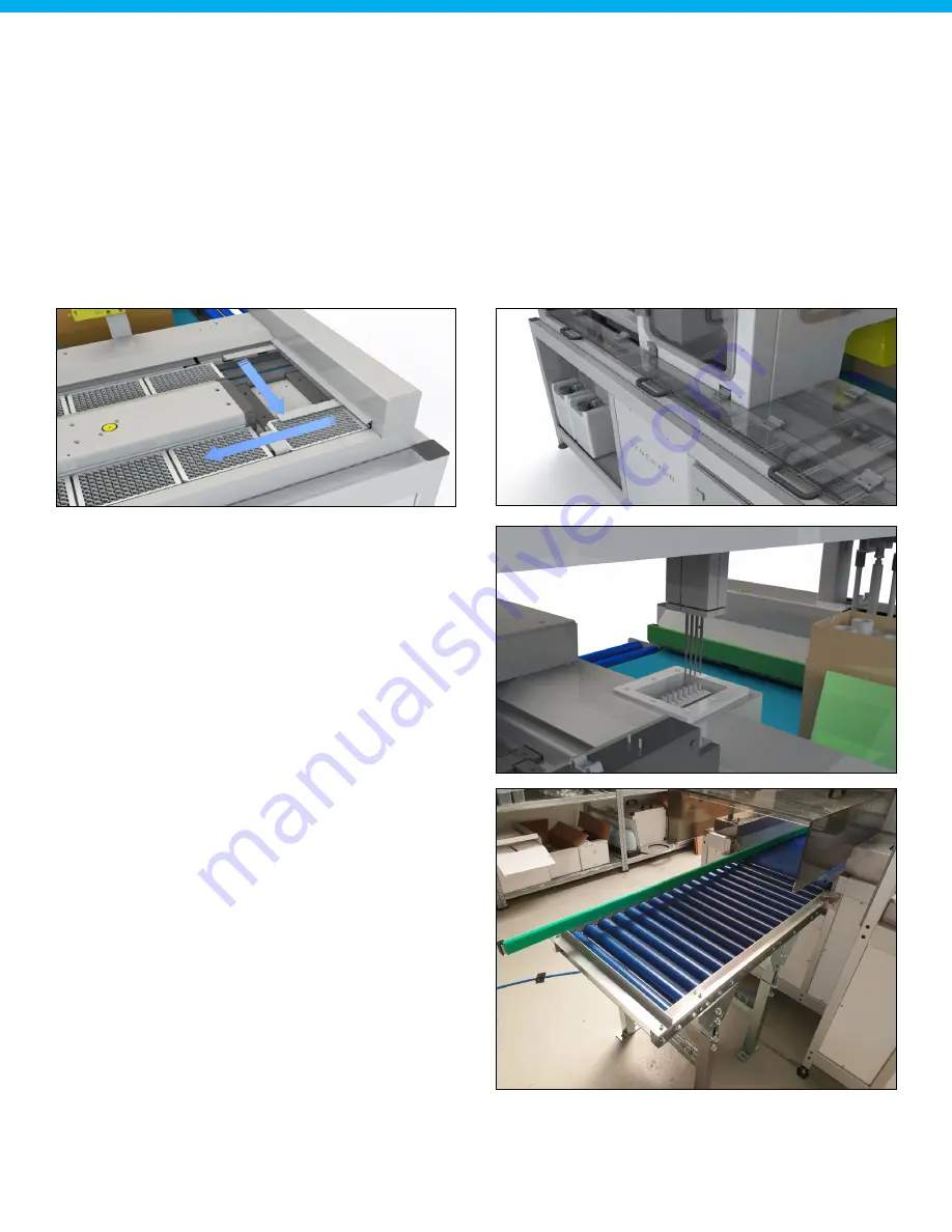
5.9. Plate output

When the shaking has been completed the plate is pushed out of the system so that the user can bring the 

final product to the analyzer for analysis. A push mechanism removes the plate from the shaker and pushes  

it out onto the plate output buffer.
The Autosampler III has an output buffer to enable continuous processing of products. The output buffer 

is filled one by one with the push mechanism described above. The buffer is accessible by opening the 

transparent panels that close off the output buffer. The panels are used to minimize the introduction of 

external particles such as dust. The panels are transparent so the user can see what panel to open in order  

to remove a plate.
A fixed sensor is positioned at the tenth plate position to alert the user and stop the machine once the output 

buffer reaches 10 plates.

5.10. Washing needles

The pipetting needles are washed in a washing module 

to prevent contamination between samples. The 

washing module washes both the external part of the 

needle as well as the inside.

5.11. Carton box outfeed

The outfeed of the system has two rollers to connect 

to an external conveyor. The system detects a correct 

outfeed, otherwise the system stops.

Summary of Contents for Autosampler III

Page 1: ...www hygiena com INS4088 REVA Autosampler III User Manual...

Page 2: ...t Installation adjustment Manual Instructions for operation Maintenance instructions Malfunctions and solutions The different parts are intended for Transport internal external Transport personnel Ins...

Page 3: ...biological material Warning Warm surface Warning Optical radiation Warning Piercing hazard Warning Strong magnetic field Warning Trip hazard Warning Automatic starting machine Warning Beware of rotat...

Page 4: ...tosampler III 14 3 3 Storage 14 4 Assembly and installation 15 4 1 Installation 15 4 2 Commissioning 15 4 2 1 Commissioning instructions general 16 4 2 2 Commissioning instructions electrical componen...

Page 5: ...Checklist prior to start priming the pumps 33 6 5 2 Start priming method 34 6 6 Loading plates 34 6 7 Pre Run 36 6 8 Lock Unlock doors 36 6 9 Starting a run 37 6 10 Main run 38 6 11 Dummies 39 6 12 Ma...

Page 6: ...3 Recipe manager 58 10 4 Top bar 59 10 5 General overview 59 10 6 Plate detail overview 61 10 7 Alarm manager overview 62 10 8 Status overview 62 10 9 User manager 63 10 10 Settings 64 11 Maintenance...

Page 7: ...71 12 7 1 General 71 12 7 2 Control word 71 12 7 3 Status word 71 12 7 4 Network 72 12 8 Channel 1 4 72 12 8 1 Single channel 72 12 8 2 All 73 12 9 Motors 74 12 9 1 Transport belt 74 12 9 2 Lift stac...

Page 8: ...the Autosampler III to normal production operations 96 16 Patch management 97 16 1 Xperimate 97 16 2 HMI 97 16 3 Windows updates 97 16 4 Installing software 97 16 5 List of drivers 98 17 Spare parts...

Page 9: ...trolled stop of the Autosampler III Besides the main lockable access door on the front the user can also access the pipetting cabinet from the side and from the back Because of this three point access...

Page 10: ...an be found on the back of the Autosampler III and are connected by means of a power plug and a pressure fitting For correct functioning of the Autosampler III the drain of the system needs to be atta...

Page 11: ...inated agents can affect these areas with prolonged use When the Autosampler III is cleaned using wet dry and or chemical means the system must always be switched off by means of the main switch Clean...

Page 12: ...ampler III it must be ensured that non load bearing parts cannot be damaged When using pallets or other forms of formwork these must be properly secured and the associated safety precautions should be...

Page 13: ...pler III 3 2 Packaging In order to ensure safe transport both for the transporter and the Autosampler III the packaging instructions must be observed When moving the Autosampler III remove all loose o...

Page 14: ...ed without using tools 3 2 3 Packaging Exterior Autosampler III To prevent damage to the outside of the Autosampler III it should be packed with the following materials Material Image Protective edge...

Page 15: ...Before unpacking and installing it is recommended to take a photo of the Autosampler III After unpacking a photo must also be taken The photos are archived and taken by both the sending and receiving...

Page 16: ...eumatic components can move 5 Machine functions Chapters 6 to 10 describe how to operate the Autosampler III This chapter provides the user with information about what functions are provided in the ma...

Page 17: ...lug that can be connected to the waste connection The layout of the fluid bay can be seen in the figure below Samples enter the machine from an external rolling conveyor The system separates the carto...

Page 18: ...the safety network 5 4 Destacking and scanning The microtiter plates are fed into the system one by one by the destacking module When a plate is destacked the plate is located at the barcode scanning...

Page 19: ...he Y Z movements and the conveyor does the X movements 5 7 Sample dispense and reagent addition The samples are dispensed into the microtiter plate per column When a column is filled the plate is move...

Page 20: ...t close off the output buffer The panels are used to minimize the introduction of external particles such as dust The panels are transparent so the user can see what panel to open in order to remove a...

Page 21: ...tialize Blue blinking Initializing or priming 5 13 Emergency stop The Autosampler III is equipped with an emergency stop right next to the control panel as well as on the right rear The emergency stop...

Page 22: ...8573 1 5 16 Description of the operator s workspace The user s workplace is indicated by the following picture The workplace is visible in the image to the right 5 17 Personal protective equipment Wh...

Page 23: ...tions and explanations regarding settings and error handling can be found in the Chapter 11 HMI and respectively Chapter 15 errors and warnings 6 1 Prepare the compressor for use Prior to the start up...

Page 24: ...rned on by means of the power switch Main switch off Main switch on Make sure there is sufficient air pressure on the Autosampler III at least 5 bar is required This can be read from the manometer whi...

Page 25: ...e taken out of operation Valve closed Valve open Turn off the main switch of the compressor The compressor is now turned off 6 2 Starting up the Autosampler III In order to start up the Autosampler II...

Page 26: ...t up possibly due to an Emergency button still being pressed no air pressure available or an unlocked door Step 4 Login to the Autosampler III When the Autosampler III is turned on the user must log i...

Page 27: ...es and remaining products The following procedure must be followed to prepare the Autosampler III for initialization 6 3 1 Checklist prior to starting Autosampler III initialization Before initializin...

Page 28: ...Empty conveyor belt Check to confirm no plates are in the outfeed roller conveyor is clear from jammed up boxes of product Free roller outfeed Check if no more plates are in the Autosampler III exclud...

Page 29: ...ces of the Autosampler III are clean according to Chapter 9 Check that the wash bath is clean according to Chapter 9 Check that the needles are free from damage If any of the above steps cannot be per...

Page 30: ...ows and make sure that all cover panels are attached Close the pipetting cabinet Door 1 front side Door 2 rear side Door 3 right side Close the shaker panel Shaker panel Make sure the cover panels are...

Page 31: ...interface press Lock Doors If the Autosampler III is locking a clicking sound is heard from the locking pins Autosampler III will be energized air will flow in and moving parts will be turned on The...

Page 32: ...pipetting channels will move up and to the back of the Autosampler III the shaker will initialize and shake for a short duration Then the pumps will be initialized against the input so liquid in the s...

Page 33: ...of air 6 5 1 Checklist prior to start priming the pumps Before priming the pumps check the following parts Sample boxes should be removed from the Autosampler III s conveyor belt Plates should be remo...

Page 34: ...pumps and pumps liquid through the tubing to prime the channels During priming of the pumps the status light will be blinking blue When the pump priming is finished the status light will be blue indi...

Page 35: ...e destacker mechanism Once the plates are in the destacker please put the cover plate see picture on top of the stack This cover plate covers the top plate provides some weight to the last plates when...

Page 36: ...un button in the control interface Pre Run button 6 8 Lock Unlock doors The Autosampler III is equipped with three automatically locking doors This section describes how these doors can be locked and...

Page 37: ...up so the system can be loaded with plates 04 Main Default run of the Autosampler III including sampling adding reagents and shaking of the plates To disable the shaker the shake time can be set to 0...

Page 38: ...1 Fill the stacker with plates using the 03 LoadPlates method see Chapter 6 6 Loading plates Make sure the plate barcodes are facing towards the right 2 Place the boxes on the Autosampler III Make sur...

Page 39: ...ed dummies should be placed in the box to fully fill it The camera will recognize the number of dummies and the Autosampler III will skip samples based on the number of detected dummies The samples th...

Page 40: ...the Autosampler III is ready to start pipetting samples For manual sampling of boxes without barcodes follow the steps listed below 1 Fill the stacker with plates Make sure the plate barcodes are faci...

Page 41: ...xes cannot be processed 7 After the manual PO is finished the last processed box will automatically move out and the plate will continue automatically After processing every plate the software creates...

Page 42: ...t of the fluid bay can be seen in the figure to the right 6 13 1 Pumps The Autosampler III is equipped with various pumps to perform the liquid handling steps within the Autosampler III This section e...

Page 43: ...ts life expectancy 6 13 1 3 Microwash pump The Autosampler III contains one diaphragm pump for pumping microwash from the 4 liter microwash container to the needle wash station 6 13 2 Chemical contain...

Page 44: ...the original position 6 Feed the tubing into the hole of the cap and make sure the tubing reaches the bottom of the tube 7 Reset the chemical usage counter on the HMI by pressing the RESET Buffer butt...

Page 45: ...Feed the tubing into the hole of the cap and make sure the tubing reaches the bottom of the tube 7 Reset the chemical usage counter on the HMI by pressing the RESET ATX button 8 Priming may be necess...

Page 46: ...ner back into the original position 6 Feed the tubing into the hole of the cap one by one and make sure the tubing reaches the bottom of the container 7 Priming may be necessary when air has entered t...

Page 47: ...n be screwed back onto the new container 5 Place the container back into the original position 6 Feed the tubing into the hole of the cap and make sure the tubing reaches the bottom of the container 7...

Page 48: ...hecklist prior to starting Autosampler III initialization Chapter 6 3 Replace the buffer and ATX tubes with microwash Replacing liquids is described in Chapter 6 12 Flush the Autosampler III with micr...

Page 49: ...ttles is prepared The bottles should be placed in the first row of the box 7 2 Starting the daily validation In order to start the daily validation of the Autosampler III please follow the steps liste...

Page 50: ...needles can move to a position where they can easily be replaced The Autosampler III should also be in idle state indicated by the blue light Step 2 Start 11 ReplaceNeedles routine Start the 11 Repla...

Page 51: ...ck into the holder Push the needle back into the holder While doing this carefully pull the tubing on top of the channel Make sure to not use too much force pulling the needle otherwise the tubing can...

Page 52: ...ee towel no paper towels to prevent scratches A microfiber towel is preferred as it captures particles well and prevents cleaning marks Never use aggressive cleaning materials such as bleach acetone a...

Page 53: ...performance but may cause dust to fall off therefore it is advised to clean this part regularly The plastic plates that are loaded into the destacker may break a little from time to time therefore th...

Page 54: ...f this procedure and specifically flushing the needle is to prevent microbiological build up crystals or precipitation of reagent within the fluid lines All these effects may interfere with test resul...

Page 55: ...emineralized water can be used Optionally ethanol can be used but only when the Autosampler III is turned off The goal of the cleaning is to remove any particles such as formed crystals or dust 4 Chec...

Page 56: ...ased products 9 8 2 Scraper The conveyor belt is equipped with a scraper to capture fluid spills that may form when piercing products To access the scraper the service panel needs to be removed using...

Page 57: ...d and all air bubbles are removed from the tubing The Flush button will initiate the cleaning process for the needles The Pre Run button can be used to update the ATP file for the Autosampler III impo...

Page 58: ...le will be in the needle Downholders default down The downholders will be in the downward position during the piercing of the sample This increases the stability of the needles but also increases the...

Page 59: ...pplication the application cannot be exited during the run of a method as indicated by the picture to the right 10 5 General overview In the general tab a simplified overview of the Autosampler III is...

Page 60: ...izes which wells have been filled Clicking the well plate opens an overview of the well plate and indicates what is in each well sample and box sources These progress bars represent the volume of the...

Page 61: ...ropdown menu on the top left side of the screen In this dropdown the 5 most recent MTPs will be displayed for quick access If an older MTP needs to be viewed the Browse button at the bottom of the dro...

Page 62: ...deleted to keep the overview clean The following is logged for each alarm Time of occurrence Time of acknowledgement Time of deletion There are three types of alarms Warning Stack light will become or...

Page 63: ...g changing and removing users A user can be updated by double tapping the row of the user needing to be edited User role is a dropdown where the specific role can be selected Pressing Ok accepts the c...

Page 64: ...machine The installation must be pressure free locally before removing the covers from the Autosampler III in order to carry out work on the system Before maintenance is carried out on an electrical i...

Page 65: ...t require periodic maintenance and need to be checked regularly for optimal use This part of the manual explains this in detail 11 2 1 Barcode scanners and camera For all photocells the visor and asso...

Page 66: ...checked daily The original color of the filter is white Contamination of the filter is recognizable by discoloration of the filter pattern yellow discoloration indicates absorption of oil Check the fi...

Page 67: ...rposes individual components that are connected to the PLC can be controlled from a web interface There are a total of 4 pages for the different components Actuators http 192 168 0 10 8080 autosampler...

Page 68: ...y sensors and their explanation Sensor Explanation Emergency The emergency circuit sensor If one of the Emergency buttons is pressed this will be deactivated Door locks The door locks circuit sensor I...

Page 69: ...r Station Sensor Detects if there is a plate at the turning module Plate Buffer Full Detects if the plate lane is full Pressure Sensor Shows if there is sufficient air pressure available Light Curtain...

Page 70: ...plates on the shaker Shaker Clamp Clamps plates onto the shaker so they are stuck while shaking 12 5 1 Cylinder control Every cylinder can be controlled in the same way Select either Out or In and pr...

Page 71: ...General Channel 1 4 12 7 1 General Using this tab the different parts on the Anybus can be controlled and checked directly using control and status words 12 7 2 Control word Using the control word dif...

Page 72: ...ition The following table contains an overview of the different parameters and their explanation Parameter Explanation Op mode Sets the channel to a specific operation mode 0 No mode change 1 Profile...

Page 73: ...ting the channels need to be homed again before they can be controlled Position Channels Using this all channels can be sent to specific positions The following table contains an overview of the diffe...

Page 74: ...lt is currently moving Error belt is in error Valid belt is homed The following table contains an overview of the different parameters and their explanation Parameter Explanation Op mode Sets the moto...

Page 75: ...erview of the minimum and maximum values for the parameters of the stacker lift Parameter Unit Min Max Position mm 0 97 Distance mm 0 97 Speed mm s 0 300 Acceleration mm s 0 600 Deceleration mm s 0 60...

Page 76: ...Using this tab the pipetting arm Z axis which pierces samples can be controlled directly See Chapter 12 9 1 Note The pipetting arm consists of two motors therefore there are two actual positions The f...

Page 77: ...shaker Reset Init Resets the homing of the parts used for handling plates on the shaker Status Yellow Warning during routine Green Successful run of routine Red Error during routine 12 10 3 Plate inpu...

Page 78: ...e pipetting arm 13 Camera jobs The following chapter describes how to create new and adjust existing camera jobs using the Cognex software In addition a list of changeable camera parameters is added t...

Page 79: ...mate are already on the correct location in the job To create a job based on the template click on File and Open Job and select the job called Job_Template job which is located on the camera s SD card...

Page 80: ...ptimize exposure settings The exposure settings of the image can be set by double clicking on cell A0 containing the image If the image is too dark the exposure can be set higher If the image is too l...

Page 81: ...e Feature threshold parameter which has a default value of 20 Using a lower threshold value translates to less fine details which is recommended for this application Adjust the parameter so that a cle...

Page 82: ...cell K2 The detected dummies will be listed in cells B43 B73 together with their detection scores If the detection is valid the valid value will be set to 1 This value is used to count the number of...

Page 83: ...erce positions needs to be done by using the PLC maintenance panel see Chapter 12 It is recommended to position the pipetting channels and the Z axis at a low speed and acceleration and with small ste...

Page 84: ...ove the samples to pierce the Z axis can be lowered with small steps to verify the pierce positions The aspiration height can also be determined Write this parameter down to later use it in the recipe...

Page 85: ...rt the move box out routine to move the box out of the system Step 13 10 Verify coordinates The list of pierce positions uses combined XY coordinates separated by a The coordinates list that will be r...

Page 86: ...Set camera online If the detection is correct and the job is finished the camera can be set back online This can be done by pressing the Online symbol The symbol should be activated after pressing it...

Page 87: ...be set offline This can be done by clicking on the online symbol if it is activated If the symbol is deactivated the camera already is offline Step 5 Open the job that needs change To open a job clic...

Page 88: ...rcing are off Needle offset H4 0 Needle offset in mm The needle offset is subtracted from the needle positions This parameter can be adjusted if all Y positions for piercing are off X positions belt C...

Page 89: ...pauses the system A pop up will indicate the steps that need to be taken by the operator to solve the problem After the problem is resolved the alarm needs to be acknowledged in the alarm manager and...

Page 90: ...Warning is added to Alarm Manager Detecting plate failed please reload plates Autosampler III retries to de stack plate Popup in HMI if still no plate was found with message Reload plates in de stacke...

Page 91: ...r s open Solve emergency Reset Emergency button Press Reset button Acknowledge alarm in the alarm manager Initialize the system before Autosampler III can be restarted Timeout during soft start Error...

Page 92: ...o be acknowledged before Autosampler III can be restarted If problem persists contact support No connection with reagent pumps Error Error is added to Alarm Manager Could not connect with reagent pump...

Page 93: ...edged Press Start to continue run Reagent 2 empty warning Warning Warning is added to Alarm Manager Warning Reagent volume 2 less than volume mL available Autosampler III will continue Reagent 2 empty...

Page 94: ...t responsible for implementing lockout tagout procedures However an authorized associate and an affected associate may be the same person when the affected associate s duties also involve performing m...

Page 95: ...rding to established procedure The tag indicates that the Autosampler III to which it is attached must not be operated until the tagout device is removed according to the energy control procedure The...

Page 96: ...g double blocking and bleeding down etc 6 Lockout and or tagout the energy isolating devices with assigned individual lock s or tag s Tags shall indicate that the energy isolated device s shall not be...

Page 97: ...ustomer Name HMI When a backup is made the required patches can be installed When the installation is done the Autosampler III should be verified to ensure that all components are working correctly Th...

Page 98: ...ct Description AUTOIII001 Needle AUTOIII002 Downholder AUTOIII003 Tubing per meter AUTOIII004 Pipetting pump AUTOIII005 Reagent pump AUTOIII006 Pipetting Syringe AUTOIII007 Reagent Syringe AUTOIII008...

Page 99: ...f the product the correct volume of products during use but also about the materials used that can burden the environment during disposal Determine what measures the user can take to minimize energy c...

Page 100: ...pection by operator orientation samples Box barcode scanned Barcode flow Box loaded into machine and vision system takes picture Recipe from PO LIMS info matches scan vision system More than 50 of tot...

Page 101: ...input file is generated from LIMS Fixed PO numbers will be added to this generated file This way there are only two situations the system needs to handle Start End Split barcode in PO number and Box...

Reviews: