www.hygiena.com
55
9.7. Pumps (syringes)
After 3 months of usage or when markings are present or performance
declines, the syringes need to be replaced.
For optimal performance check the fluid connections on a regular basis. The
fittings, also known as lock nuts, should not be wet nor have visible precipitation
of chemicals. The syringe glass should not have markings. A tiny amount of
liquid may be present underneath the plunger a small hole is present to allow for
air to enter and for some evaporation to occur. If liquid persists to be underneath
the syringe or a pool of fluid is formed, the syringe needs to be replaced.
When the lock nuts are wet, or crystals have built up around the connectors,
inspection is due. Remove the couplings as follows:
1.
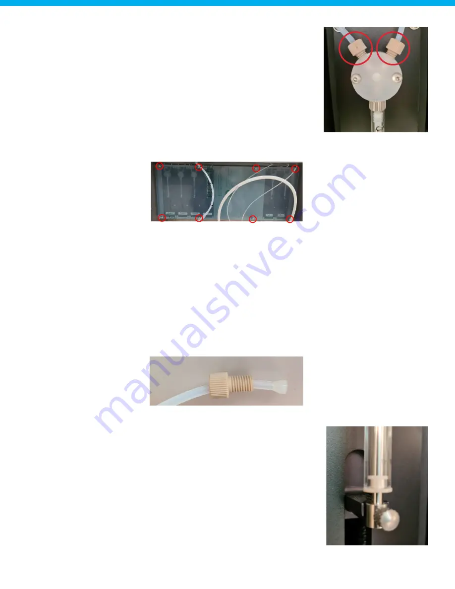
Remove the cover plate using a size T20 Torx screwdriver.
2.
Turn the locknut counterclockwise and have a lint free towel avaliable to capture any fluid that is inside
the locknut.
3.
Clean the inside of the locknut using a lint free towel. Demineralized water can be used. Optionally,
ethanol can be used, but only when the Autosampler III is turned off. The goal of the cleaning is to
remove any particles such as formed crystals or dust.
4.
Check the ferrule for wear. A correct ferrule should not be deformed and has a conical shape.
5.
Replace the ferrule, if needed, so that it is attached as pictured below.
6.
Insert the tubing so that the flat part of the ferrule sits against the back of the port.
7.
Screw the lock nut in place by turning it clockwise. Screw until hand tight, no tools are needed.
Replace the syringe.
To replace the syringe, the following steps must be performed.
1.
Start the "replace syringe routine" in the interface. This moves
the plunger down.
2.
Remove the cover plate in front of the syringes.
3.
Remove the screw on the plunger by turning it counterclockwise.
4.
Remove the syringe barrel by turning it counterclockwise.
5.
Attach a new syringe by turning it clockwise.
6.
Attach the plunger screw by turning it clockwise.
7.
Reattach the cover plate.
8.
Perform an initialization routine (Chapter 6.3).
Picture of one pump displaying the lock nuts
Picture of cover plate and screw points
Ferrule attached correct
Plunger screw


