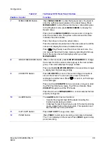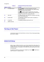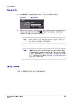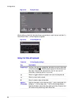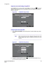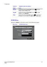
background image

Configuration

42

Use the UP and DOWN arrows to change the number. Use the LEFT and RIGHT 
arrows to move between hour, minutes, and seconds. Press 

 when you have 

the correct time.

5.

Highlight the Format field beside Time and press 

. Select from the three 

available time formats and press 

 to save the selected format.

Note

The clock does not start running until you highlight Save and 
press .

6.

Highlight the field beside Time Zone and press 

. Select the correct time zone 

from the list and press 

.

7.

Highlight Use Daylight Saving Time and press 

 to toggle between On and 

Off

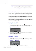
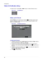
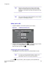
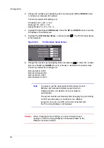
Setting Holidays

1.

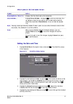
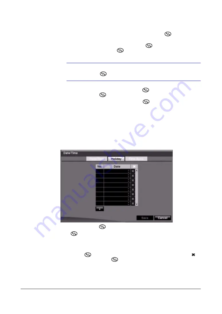
Highlight the Holiday tab, and the Holiday setup screen appears.

Figure 3-11

Holiday Setup Screen

2.

Highlight + and press 

. The current date appears.

3.

Press 

 again to change the date. Use the LEFT and RIGHT arrows to toggle 

from month to day. A white box highlights use the UP and DOWN arrows to 
change the number values.

4.

Highlight the month and day, and change them by using the UP and DOWN 
arrows. Press 

 to add the date. Dates can be deleted by highlighting the   

beside the date and pressing 

.

Summary of Contents for HRSD16

Page 1: ...Document 800 03650 Rev D 02 09 User Guide HRSD8 HRSD16 8 16 Channel Models Color Digital Video Recorder ...

Page 2: ...Rev A 12 08 New document Rev B 12 08 Added Appendix D to Introduction chapter changed image for figure 3 5 made some text changes Rev C 01 09 Corrected an Alarm In specification Rev D 02 09 Changed back cover minor changes throughout ...

Page 3: ...xpressly approved by the party responsible for compliance could void the user s authority to operate the equipment This Class A digital apparatus complies with Canadian ICES 003 Cet appareil numérique de la Classe A est conforme à la norme NMB 003 du Canada CE Compliance This equipment has been tested in accordance with the following directives EN55022 2006 Class A EN50130 4 1995 A2 2003 EN61000 3...

Page 4: ...ypes of wastes and recycle it responsibly to promote the sustainable reuse of material resources Household users should contact either the retailer where they purchased this product or their local government office for details of where and how they can take this item for environmentally safe recycling Business users should contact their supplier and check the terms and conditions of the purchase c...

Page 5: ...Through Video 24 Connecting Audio 25 Connecting the Monitor 25 Connecting the DVR for Remote Access 26 Connecting Alarm Inputs and Outputs 27 Connecting USB Ports 28 Factory Reset 29 Connecting the Power Cord 29 3 Configuration 31 Front Panel Controls 31 Turning on the Power 34 Initial Unit Setup 34 Logging In 35 Setup Screen 35 Network Notification Setup 52 Configuring Devices 62 Recording Settin...

Page 6: ...e USB hard disk drive in Windows Vista 139 Appendix B Text In Query Examples 141 Query Example I 141 Query Example II 142 Appendix C Reviewing Video Clips 143 Appendix D WebGuard 147 Computer System Requirements 147 Launching WebGuard 149 Using WebWatch for Web Monitoring 150 Using WebSearch to Search Recorded Video 153 Appendix E Time Overlap 157 Appendix F Troubleshooting 159 Appendix G Connecto...

Page 7: ...t Input Connectors 28 Figure 2 13 USB Ports 28 Figure 2 14 Factory Reset Switch 29 Figure 2 15 Power Cord Connector 29 Figure 3 1 16 Channel DVR Front Panel 31 Figure 3 2 Login Screen 35 Figure 3 3 Setup Screen 36 Figure 3 4 Virtual Keyboard 36 Figure 3 5 Information Screen 37 Figure 3 6 Upgrade Screen 38 Figure 3 7 Setup Import Screen 39 Figure 3 8 Setup Export Screen 39 Figure 3 9 System Log Scr...

Page 8: ...ort Setup Window 65 Figure 3 38 Audio Setup Screen 65 Figure 3 39 Alarm Out Settings Screen 66 Figure 3 40 Alarm Out Schedule Screen 67 Figure 3 41 Display OSD Screen 69 Figure 3 42 OSD Margin Screen 70 Figure 3 43 Main Monitor Screen 70 Figure 3 44 Spot Monitor Screen 72 Figure 3 45 Remote Control Setup Screen 72 Figure 3 46 Record Menu 73 Figure 3 47 Record Setup Screen 74 Figure 3 48 Schedule S...

Page 9: ...Setup Screen 103 Figure 3 78 System Event Actions Screen 105 Figure 3 79 Event Status Screen 106 Figure 4 1 DVR Front Panel and Controls 107 Figure 4 2 Page Sequence 111 Figure 4 3 Mouse Menu 112 Figure 4 4 Mouse Display Menu 113 Figure 4 5 Sequence Menu 115 Figure 4 6 PTZ Select Camera Menu 116 Figure 4 7 PTZ Preset Screen 117 Figure 4 8 Preset View Screen 118 Figure 4 9 PTZ Toolbar 118 Figure 4 ...

Page 10: ...151 Figure D 3 WebSearch Screen 154 Figure E 1 Time Overlap 157 Figure E 2 Time Overlap Segment Selection 157 Figure E 3 Time Overlap Start Stop Time Selection 157 Figure G 1 I O Connector Pinouts 161 Figure G 2 RS485 Connector Pinouts 161 ...

Page 11: ...Table 3 11 Record Setup Screen Options 74 Table 3 12 Motion Detection Zone Setup Screen Menu 86 Table 4 1 Front Panel Controls 107 Table 4 2 Mouse Functions 112 Table 4 3 Right Mouse Button Menu Functions 112 Table 4 4 Mouse Display Menu Functions 113 Table 4 5 PTZ Toolbar Tools 118 Table 4 6 Playback Button Functions 121 Table 4 7 Playback Toolbar Functions 122 Table 4 8 Search Menu Options 123 T...

Page 12: ...Tables 12 ...

Page 13: ... overview of its components Chapter 2 Installation describes how to install the DVR and connect the system components Chapter 3 Configuration provides an overview of the front panel controls and LCD displays and provides instructions for configuring the DVR Chapter 4 Operation describes live monitoring recording video and audio playing recorded video and searching for video Appendix A USB Hard Dis...

Page 14: ...ts common terms and the pages where they appear About Cautions and Warnings Caution A caution advises users that failure to take or avoid a specified action could result in loss of data or damage to the equipment WARNING A warning advises users that failure to take or avoid a specified action could result in physical injury to a person or irreversible damage to the equipment Important Safeguards 1...

Page 15: ...rom the type of power source indicated on the marking label If you are not sure of the type of power please consult your equipment dealer or local power company 8 Power Cords Operator or installer must remove power BNC alarm and other connections before moving the equipment 9 Lightning For added protection for this equipment during a lightning storm or when it is left unattended and unused for lon...

Page 16: ...zed substitutions may result in fire electric shock or other hazards 15 Safety Check Upon completion of any service or repairs to this equipment ask the service technician to perform safety checks to determine that the equipment is in proper operating condition 16 Field Installation This installation should be made by a qualified service person and should conform to all local codes 17 Correct Batt...

Page 17: ...is document uses the following typographical conventions Font What it represents Example Helvetica Keys on the keyboard Press Ctrl C Lucida Values of editable fields that are mentioned in the body text of the document for referene purposes but do not need to be entered as part of a procedure The Time from field can be set to Hours Minute Seconds Text strings displayed on the screen Syntax The mess...

Page 18: ...18 ...

Page 19: ...PAL Loop Through Video Connectors Continuous Recording in Disk Overwrite Mode 2 USB 2 0 Ports Continues Recording while Transmitting to Remote Site and during Playback User friendly Graphical User Interface GUI Menu System Multiple Recording Modes Time lapse Pre event Alarm Motion Text and Panic 2 Channel Audio Recording and 1 Channel Audio Playback Text Input for ATM and POS Alarm Connections Inc...

Page 20: ...indexed by time or events and you can instantly view video after selecting the time or event Your DVR can be set up for event or time lapse recording You can define times to record and the schedule can change for different days of the week and user defined holidays The DVR can be set up to alert you when the hard disk drive is full or it can be set to record over the oldest video once the disk is ...

Page 21: ...R Installation for the HRSD8 16 DVR Sensors 1 16 VGA Out Cameras 1 16 Main Monitor BNC Spot Monitor Audio Input 1 2 Audio Output USB HDD CD RW Flash Drive Digital Video Recorder Alarm Output 1 2 Flashing Light Siren ATM POS Remote Keyboard Mouse RASplus WebGuard Network ...

Page 22: ...Introduction 22 ...

Page 23: ...ngual User Guide RASplus CD ROM RASplus User Guide Multilingual RASplus Software CD and User Guide RASplus CD ROM DVRNS Server Software and User Guide RASplus CD ROM Rack mount Kit Required Installation Tools No special tools are required to install the DVR Refer to the installation manuals for the other items that make up part of your system Figure 2 1 16 Channel DVR Rear Panel ...

Page 24: ...ct your video source to another device you can use the Loop BNC connectors Figure 2 3 Video Loop Through Connectors Note The Loop BNC connectors are auto terminated Do NOT connect a cable to the Loop BNC unless it is connected to a terminated device because it will cause poor quality video Table 2 1 Rear Panel Connections Connection Connection 1 Video input 6 Network Ethernet port 2 Looping connec...

Page 25: ... have amplified audio output so you need a speaker with an amplifier The DVR does not have a pre amplifier for audio input so the audio input should be from an amplified source not directly from a microphone Connecting the Monitor Using a Computer Monitor A VGA connector is provided so that you can use a standard multi sync computer monitor as your main monitor Use the cable supplied with your mon...

Page 26: ...or to connect to the DVR See Chapter 3 Configuration for how to configure the modem Figure 2 7 RS232C Port Note The DVR is not supplied with a modem cable and many modems are not supplied with cables Ensure that you have the correct cable when purchasing the modem Connecting the Network Port The DVR can be networked using the 10 100Mb Ethernet connector Connect a Cat5 cable with an RJ45 jack to th...

Page 27: ...S485 Port Connecting Alarm Inputs and Outputs Note To make connections on the Alarm Connector Strip press and hold the button and insert the wire in the hole below the button After releasing the button tug gently on the wire to ensure that it is connected To disconnect a wire press and hold the button above the wire and pull out the wire Figure 2 10 Alarm Input Connectors AI 1 to 16 Alarm In You c...

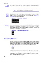
Page 28: ...Ground connectors The threshold voltage is below 0 3V and should be stable at least 0 5 seconds to be detected Connect the wires to the ARI Alarm Reset In and GND Ground connectors Figure 2 12 Alarm Reset Input Connectors Connecting USB Ports Two USB ports on the front panel are provided to connect external hard disk CD RW or flash drives for video clip copying or system upgrades Position external...

Page 29: ...rclip 1 Turn off the DVR 2 Turn it on again 3 While the DVR is initializing the front panel LEDs blink When the front panel LEDs blink poke the straightened paperclip to the unlabeled hole in the left of the Alarm Output connectors 4 Hold the switch until all the LEDs on the front panel are lit Note When the DVR successfully resets to factory defaults all the LEDs on the front panel flash five tim...

Page 30: ...in receptacle do not modify the plug Do not overload the circuit by plugging too many devices in to one circuit Caution In noisy electrical environments use an Uninterruptible Power Supply UPS to minimize the potential of damage to the DVR from undesired power related hazards Connect the UPS between the DVR and the AC voltage supply Your DVR is now ready to operate See Chapter 3 Configuration for ...

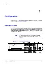
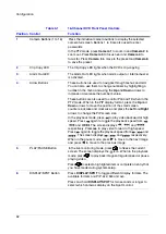
Page 31: ...multiplexer Many of the buttons have multiple functions The following describes each button and control Take a few minutes to review the descriptions You will use these to initially set up your DVR and for daily operations Note You can also use a USB mouse not supplied to navigate through the screens and menus much like you would on a computer Figure 3 1 16 Channel DVR Front Panel 1 9 1 0 1 1 1 2 ...

Page 32: ... in the PIP display format press the Up and Down arrows to move the position of the small screen counter clockwise and clockwise and press the Left and Right arrows to change the PIP screen size In the playback mode press to play video backward at high speed Press again to toggle the playback speed from and The screen displays and respectively Press to play video forward at high speed Press again ...

Page 33: ...creen displays the page number Press and hold GROUP SEQUENCE for two seconds or longer to display live channels sequentially 9 ZOOM PTZ Button Press ZOOM PTZ to zoom in the current image to double its size on the screen You can use the arrows to move the rectangle to another area Press to zoom in on the image in the rectangle Press and hold ZOOM PTZ for two seconds or longer to enter the PTZ Pan T...

Page 34: ...y Pause to reset that screen to its default settings 13 PLAYBACK Button Press PLAYBACK to enter the playback mode Press PLAYBACK again to exit the playback mode When entering the playback mode video is paused Press to play back video at regular speed The screen displays when the DVR is in the Pause mode and the screen displays when the DVR is playing back video 14 HDD LED The HDD LED flickers when...

Page 35: ...ord when logging in the Admin User for the first time Note To assure the secure management of the system setting up a password is strongly recommended Note Instead of using the front panel buttons you can use a mouse not supplied to access the Login screen Click the right mouse button to display the Login screen Click to enter a password The virtual keyboard appears See Using the Virtual Keyboard ...

Page 36: ... in the name or title and press That character appears in the title bar and the cursor moves to the next position You can use up to 31 characters including spaces in your title Press to toggle between the upper and lower case keyboards Press to move back a space Press to delete entered characters Special Characters Special characters can be created using and a capital letter For example J for NL N...

Page 37: ...tion Screen 2 Highlight the Site field in the Information screen and press A virtual keyboard appears that you can use to enter a Site Name 3 Highlight Close and press once you have entered your title 4 Highlight the field beside System ID and press To change the number highlight it and use the Up and Down arrows to choose from 0 to 99 Note The System ID number is used to identify the unit when it...

Page 38: ...tes that the file is for software upgrades ofi indicates that the file is for optical drive firmware upgrades 3 Select the desired file and press 4 Highlight Install and press to install the selected software package 5 Highlight Cancel and press to close the window without upgrading the software You get an error message if the upgrade package file is not installed correctly on the DVR The system r...

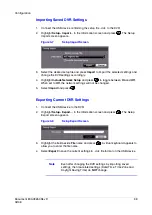
Page 39: ... between On and Off When set to Off the network settings will not be changed 5 Select Import and press Exporting Current DVR Settings 1 Connect the USB device to the DVR 2 Highlight Setup Export in the Information screen and press The Setup Export screen appears Figure 3 8 Setup Export Screen 3 Highlight the field beside File name and press A virtual keyboard appears to allow you to enter the file...

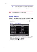
Page 40: ...atest It lists them from the latest activity and includes the time and date of each event The icon displays in the last column for system activities from the remote site 1 Highlight Show System Log in the Information screen and press to display the System Log Figure 3 9 System Log Screen 2 Select log entries by either scrolling through the log pages by using the UP and DOWN arrows or by choosing a...

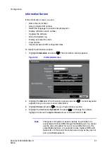
Page 41: ... to save the selected format 4 Highlight the first field beside Time and press to scroll through the individual sections of the time Option Action Recorded Data From To Displays the time information of recorded data Clear All Data Highlight Clear All Data and press to clear all video data You are asked to verify that you wish to clear all data before the DVR erases the video data Clear All Data do...

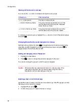
Page 42: ... Select the correct time zone from the list and press 7 Highlight Use Daylight Saving Time and press to toggle between On and Off Setting Holidays 1 Highlight the Holiday tab and the Holiday setup screen appears Figure 3 11 Holiday Setup Screen 2 Highlight and press The current date appears 3 Press again to change the date Use the LEFT and RIGHT arrows to toggle from month to day A white box highl...

Page 43: ...erver and Interval fields become active 3 Highlight the field beside Time Server and press Use the virtual keyboard to enter the IP address or domain name of the time server Note You can use the domain name instead of the IP address if you have already set up the DNS Server when setting up the LAN 4 Highlight the field beside Interval and press Set the time interval for synchronization from 30 min...

Page 44: ...s the storage device Capacity The Capacity column displays the capacity of the storage device Format Use this field to format the storage device The Format column displays whether the device is used for recording Record or not Not Using Not Formatted indicates the device is not formatted indicates when the device has temporary space set aside so that video clips can be saved on a CD RW or DVD RW S...

Page 45: ...nently deletes all video audio text and other information stored in the hard drive This information is not recoverable Note The DVR does NOT support USB hard disk drives with a version lower than 2 0 Note System hard drive capacity upgrades require formatting internal hard disk drives Using the Information Column In the Information column you can find the time and date information for the recorded...

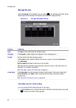
Page 46: ...een displays Figure 3 16 Storage Status Screen Table 3 3 Storage Status Information Column Information Type The Type column displays the type of storage device Disk Bad The Disk Bad column displays the percentage of bad sectors Not Formatted indicates the device is not formatted Temperature The Temperature column displays the temperature of the storage device S M A R T The S M A R T column display...

Page 47: ...M A R T information is available only for internal hard disk drives that support the S M A R T Self Monitoring Analysis and Reporting Technology monitoring program Select Close and press to exit the Storage Status screen User Setup Screen The User setup screen displays the authorized groups and users You can add and delete groups and users When adding a group you can assign authority levels to the...

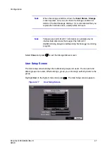
Page 48: ...so change the group to which the user is assigned Caution Write down the new password and save it in a secure place If the password is forgotten the unit must be reset using the Factory Reset Button and all data settings will be lost Deleting a User or an Entire Group Use the column to delete a User Name or an entire Group If the is grayed out then that Group or User cannot be deleted 1 Highlight ...

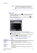
Page 49: ...the group in the New Group setup screen To change all authority levels of the group highlight the Authority field and press to toggle between On and Off To change the authority level of a single User highlight the individual authority level boxes and press to toggle between On and Off The authority levels that can be turned On and Off are shown in Table 3 4 Table 3 4 New Group Authority Level Assi...

Page 50: ...Z Control The user can control the PTZ camera on a local system or a PC running RASplus Alarm Out Control The user can reset the DVR outputs including the internal buzzer that plays during an alarm by pressing the ALARM button on a local system or alarm out control button on a PC running RASplus Covert Camera View The user can view video from cameras set to Covert while in the Live Monitoring or S...

Page 51: ...t Never 1 min 3 min 5 min 10 min 15 min 20 min 25 min 30 min and 1 hr Save your changes by highlighting Save and pressing the button Select Cancel to exit the screen without saving the changes Shutting Down the DVR 1 Highlight Shutdown in the System menu and press The Shutdown screen displays asking you to confirm whether or not you want to shut the system down Figure 3 20 Shutdown Screen 2 Select...

Page 52: ...AN Modem and DVRNS settings Figure 3 23 Network Setup Screen Configuring the Network 1 Highlight the first field beside Transfer Speed Press the Up and Down arrows to set the Transfer Speed from 50 Kbps to 100 Mbps 2 Highlight the second field beside Transfer Speed You can select the unit of measure for the transfer speed between bps and ips Press to set the unit of measure 3 Highlight the field b...

Page 53: ... 1 Highlight the LAN tab The LAN Manual Setup screen displays Figure 3 24 LAN Manual Setup Screen 2 Highlight the field beside Type and press You can select the type of network configuration from Manual DHCP and ADSL with PPPoE Select the desired type and press Configuring the LAN Parameters Manually 1 Select Manual from the LAN Type field to set up LAN parameters manually Note You need to get the...

Page 54: ... to select the number field Use the UP and DOWN arrows to increase or decrease the number value The factory default Port settings are Remote Admin 8200 Remote Callback 8201 Remote Watch 8016 Remote Search 10019 Note You need to get the appropriate Port Numbers for each RASplus and webGuard related program Admin Callback Watch and Search from your network administrator The system restarts automatic...

Page 55: ...P address of the DVR Figure 3 26 LAN DHCP Setup Screen Configuring the LAN Using ADSL 1 Select ADSL with PPPoE in the LAN Type field The LAN ADSL setup screen appears Note ADSL and modem cannot be configured at the same time If the DVR is configured by modem the ADSL with PPPoE can not be selected Figure 3 27 LAN ADSL Setup Screen 2 Highlight the field beside ID and press A virtual keyboard appear...

Page 56: ...might change whenever the unit is turned on Setting Up the Modem Highlight the Modem tab in the Network screen and the Modem screen appears Figure 3 28 Modem Setup Screen Note If the RS232C port is in use for remote control networking cannot be configured for a modem Table 3 5 Modem Setup Screen Options Option Action Enable Highlight Enable and press to toggle between On and Off You can only chang...

Page 57: ...creen Data Bit Highlight the field beside Data Bit and press Choose between 7 bit and 8 bit formats Stop Bit Highlight the field beside Stop Bit and press Choose between 1 and 2 Stop Bits Parity Highlight the field beside Parity and press A drop down list appears You can select from None Odd or Even parity Table 3 5 Modem Setup Screen Options Option Action ...

Page 58: ...ter the IP address or domain name of the DVRNS server Note You need to get the IP Address or domain name of the DVRNS Server from your network administrator Note You can use the domain name instead of IP address if you already set up the DNS Server when setting up the LAN Port Highlight the field beside Port and press Set the port number of the DVRNS server using the Up and Down arrows to increase...

Page 59: ...rmation of the DVRNS server in the box beside Help Desk WebGuard Setup To set up WebGuard 1 Highlight the WebGuard tab The WebGuard screen displays Figure 3 30 WebGuard Screen 2 Highlight Use WebGuard Service and press to toggle between On and Off See Appendix D WebGuard for detailed descriptions of the WebGuard service 3 Highlight the box beside Port and press Set the port number used when access...

Page 60: ...ou can make changes to the settings only if Mail is enabled SMTP Server Highlight the field beside SMTP Server and press Use the virtual keyboard to enter the SMTP Server IP address or domain name obtained from your system administrator Note You need to get the IP Address or domain name of the SMTP Server from your network administrator Note You can use the domain name instead of the IP address if...

Page 61: ...e and press to toggle between On and Off 3 Highlight the field beside User Password and press Use the virtual keyboard to enter the user ID and password Sender Highlight the field beside Sender and use the virtual keyboard to enter the sender s e mail address Note The e mail address must include the character to be a valid address Recipient Highlight the field beside Recipient and use the virtual ...

Page 62: ...nter the number of times you would like the DVR to try contacting the computer You can select from 1 to 10 retries Modem If the modem was enabled in the Network screen see Setting Up the Modem on page 56 you can set the DVR to contact a computer running RASplus Highlight Modem and press to toggle between On and Off When Modem is turned On you can enter a telephone number Remote Server Phone Number...

Page 63: ... select the field under No and press To change the Title of each camera highlight the name under the Title column and use the virtual keyboard To determine which cameras display on the monitors select Normal Covert 1 or Covert 2 from a drop down list in the Use column Note If you select Covert 1 the DVR displays the camera title and status icons on the covert video If you select Covert 2 the DVR d...

Page 64: ... to the PTZ List 1 Highlight the PTZ tab and the PTZ setup screen displays Figure 3 35 Camera PTZ Setup Screen Note You can only set up PTZ devices if the PTZ port is set to RS232C or RS485 You can not use a modem if you are using the RS232C port for PTZ control 2 Highlight the field in the Product column for the PTZ camera you wish to configure and press A list of PTZ devices appears Figure 3 36 ...

Page 65: ...rom 0 to 256 Configuring a PTZ Camera in the Port Setup Window After selecting a Port in the PTZ tab you can configure PTZ up to 16 cameras 1 Highlight the Setup field and press The Port Setup window appears Figure 3 37 Port Setup Window 2 Configure the port settings based on the PTZ camera manufacturer s instructions 3 Save your Camera changes by highlighting Save and pressing Select Cancel to ex...

Page 66: ...Note The DVR does NOT record audio when the recording speed is set to less than 1 ips 4 Save your Audio changes by highlighting Save and pressing Select Cancel to exit the screen without saving the changes Alarm Out Screen The Alarm Out screen allows you to change the settings and to establish a schedule for each alarm output from the back of the DVR Highlight Alarm Out in the Devices menu and pre...

Page 67: ...ion Title Each alarm output can be given its own title by highlighting the field under the Title heading and pressing A virtual keyboard appears with which you can enter the title Type Highlight the fields under the Type heading to set the alarm output for NO or NC normally open or normally closed Dwell Time Highlight the field beside Dwell Time and press to set the dwell time of the alarm output ...

Page 68: ...n the No column the higher it s priority Day Use the Day field to select the days that the alarm schedule are active The choices are Sun Mon Tue Wed Thu Fri Sat M F Hol and All Range Use the Range field to set the time in 15 minute increments from 00 00 to 24 00 that the alarm schedule is active Mode Use the Mode field to set how the alarm reacts during the scheduled time When set to On the Alarm ...

Page 69: ...ce mode Screen Group The number of screen group displays when the DVR is not in the 4x4 display mode of the 16 channel DVR and 3x3 mode of the 8 channel DVR Free Space displays when the DVR is in the Recycle mode The percentage of available storage space displays when the DVR is not in the Recycle mode Date Time Displays the current date and time information User Name Displays the name of the curr...

Page 70: ...just the display dwell time for each camera displayed on the main monitor define the screen layout in a variety of formats set the DVR to sequence through the different screen layouts pages so that all the cameras are displayed set up the DVR to display one camera or a group of cameras all the time while cycling through the remaining cameras in a Cameo window Highlight the Main Monitor tab to swit...

Page 71: ...o display one camera or a group of cameras all the time while cycling through the remaining cameras in a Cameo window This can be done with one camera displayed full screen while displaying the cameo window as a PIP picture in picture or displaying the cameras in a grid pattern with the bottom right window as the cameo Note Sequence cannot be used in the 4x4 display mode of the 16 channel and 3x3 ...

Page 72: ...the cameras On and Off 4 Select the Dwell time by highlighting that field and pressing You can select from 1 to 20 seconds Save your Display settings by highlighting Save and pressing Select Cancel to exit the screen without saving the changes Remote Control Screen With the Remote Control Setup screen you can select a port and make correct settings for a remote keyboard 1 Highlight Remote Control ...

Page 73: ...e field beside Remote Control Product and select the device from the list Save your Remote Control settings by highlighting Save and pressing Select Cancel to exit the screen without saving the changes Recording Settings Your DVR offers a variety of flexible recording modes You can set it to Record all the time Record only events Continue recording once the hard disk drive is full by recording ove...

Page 74: ...ord Dwell field and set the length of time you would like to record for the associated event You can set the dwell from 5 seconds to 15 minutes See Event Settings on page 79 in this chapter for information regarding event recording Auto Deletion Highlight the slide bar beside Auto Deletion and use the Left and Right arrows to adjust the length of time recorded data is kept from Never to 1 to 99 da...

Page 75: ... Recording Duration field and set the duration of panic recording You can set the dwell from No Limit to 5 minutes to 1 hour Panic recording stops automatically after the preset duration as long as the PANIC button is not pressed to stop the panic recording Select No Limit if you want to stop panic recording manually Panic Recording ips Highlight the Panic Recording ips field and press to set the ...

Page 76: ...een to indicate that the schedule is turned off The Panic recording works even when Schedule is turned off displays during panic recording Highlight the and press to add a schedule item Note The higher the number in the No column the higher it s priority Day Highlight the field under the Day heading and press to change the days that the scheduled recording takes place Choose from Sun Mon Tue Wed T...

Page 77: ... red icon displays at the top left corner of the screen The DVR records and displays the icon at the top left corner of the screen when any event occurs When the DVR is in the Pre Event recording mode the yellow icon displays when there is no event and the DVR is not recording When the DVR is in the Pre Event mode the red and display when any event occurs and the DVR starts recording When the DVR ...

Page 78: ...ow to handle pre event recording In the Pre Event setup screen you can do the following Turn individual cameras On or Off for pre event recording Set the image speed from a range of 0 10 to 30 00 ips 25 00 ips PAL Set the image quality to Very High High Standard or Basic Set the amount of time to record prior to the event by adjusting the Dwell time Set the Dwell duration from a range of 5 seconds...

Page 79: ...ant recorded with that event You can set what the DVR does when an alarm output is detected which can include an internal DVR buzzer You can also set notification actions On the Actions 2 tab you can select PTZ pan tilt zoom presets for each camera and you can assign spot monitors to cameras Figure 3 51 Event Menu Alarm In Screen The alarm terminal strip on the back of the DVR has inputs associate...

Page 80: ...Select which alarm input you want associated with panic recording by scrolling with the UP and DOWN arrows then press Note If panic recording is triggered as a result of the settings from the Alarm In menu then the DVR continues recording until input on the selected alarm stops You can also press PANIC on the DVR to stop panic recording Setting the DVR Actions in Response to Alarm Input You can se...

Page 81: ...e in the Record Schedule setup screen Setting Alarm Out Actions 1 Highlight the desired field under the Alarm Out heading and press The Alarm In 1 Alarm Out screen appears 2 Select the Alarm Output connectors that you would like to activate whenever the DVR detects an input on the associated alarm input 3 Turn On or Off the internal buzzer of the DVR When set to On the internal buzzer beeps when a...

Page 82: ...the individual items On and Off by highlighting them and pressing 3 Highlight OK and press to accept your changes Note For the Notify action the notify item you select should be enabled in the Notification setup screen and the DVR should be registered in the RASplus Remote Administration System Actions 2 Setup Screen In the Alarm In Actions 2 tab you can choose PTZ camera preset positions and spot...

Page 83: ...set column Press to open a list of Presets 3 Scroll through the list using the UP and DOWN arrows and then press to select the preset 4 Select the PTZ preset from the list Associating Spot Monitors with Cameras A Spot monitor can be associated with a camera The DVR displays the associated camera on the Spot monitor whenever it detects input on the associated alarm input 1 Highlight the desired fie...

Page 84: ... the cameras the Alarm Out output connectors and the notification actions for each Alarm In input connectors In the Motion Detection Actions 2 tab you can choose PTZ camera preset positions and spot monitor actions Motion Detection Settings Tab Highlight Motion Detection in the Event menu and press The Motion Detection setup screen appears Figure 3 56 Motion Detection Settings Screen Adjusting the...

Page 85: ...mage where you want to detect motion For example you can choose to detect motion in and around a doorway 1 Highlight the field under the Zone heading in the Motion Detection Settings screen and press The Motion Detection Zone screen appears Figure 3 58 Motion Detection Zone Screen The Motion Detection Zone screen is laid over the video for the selected camera 2 Select or clear blocks to set up the...

Page 86: ...ding in the Motion Detection Settings screen and press The Motion Detection Min Blocks screen appears 2 Use the UP and DOWN arrows to independently adjust the minimum number of detection blocks for Daytime and Nighttime Smaller numbers provide greater sensitivity because fewer detection blocks must be activated Select Activates highlighted blocks to detect motion Clear Deactivates highlighted bloc...

Page 87: ...e list Now the DVR will not log and notify motion events that occurred during the preset interval range Setting Up Sensitivity Levels for the Daytime Range 1 Highlight the Daytime Setup field in the Motion Detection Settings screen and press to set up the Daytime range The Daytime Setup Screen appears Figure 3 60 Daytime Setup Screen 2 Highlight the field beside Daytime and press 3 Use the UP and ...

Page 88: ...ple cameras with a camera that detects motion Selecting a Camera or Cameras for Recording 1 Highlight the desired field under the Record heading and press A list of cameras appears 2 Select the cameras that you want the DVR to record when the DVR detects motion on the selected camera If the DVR detects motion on the selected camera it starts recording video from all the associated cameras Note For...

Page 89: ...ut setup screen Schedule tab Setting Motion Detection Notifications 1 Highlight the desired field under the Notify heading and press The Motion Detection Notify menu appears 2 You can toggle the entire list On and Off by highlighting Notification and pressing You can toggle the individual items On and Off by highlighting them and pressing 3 Highlight OK and press to accept your changes Note For th...

Page 90: ...to move whenever the DVR detects motion on the selected camera 1 Highlight the desired field under the PTZ heading and press The Motion Detection 1 PTZ setup screen appears 2 Select the PTZ field next to the desired camera and press A list of PTZ presets appears Figure 3 63 PTZ Preset Screen 3 Select the PTZ preset from the list 4 Select OK and press to load the settings ...

Page 91: ...hting Save and pressing Select Cancel to exit the screen without saving the changes Video Loss Screen You can use the Video Loss function to see if anything is obscuring the camera The DVR can be set to react to video loss differently for each camera Each camera can be associated with other cameras trigger an Alarm Out connector sound the DVR internal buzzer notify a number of different devices mo...

Page 92: ...reen Selecting a Camera or Cameras for Recording You can set the DVR to start recording video from all the associated cameras if the DVR detects video loss on the selected camera 1 Highlight the desired field under the Record heading and press A list of cameras appears 2 Select as many cameras as you wish to associate with that camera to have the DVR to record when video loss is detected If the DV...

Page 93: ...ectors that you would like to activate whenever the DVR detects video loss on the selected camera 3 Select OK and press to accept the changes Note For the Alarm Out action the alarm output and beep you select should be set to the Event mode in the Alarm Out setup screen Schedule tab Setting Video Loss Notifications 1 Highlight the desired field under the Notify heading and press The Video Loss Not...

Page 94: ...ts You can preset the position for each PTZ camera and to where you want each PTZ camera to move whenever the DVR detects video loss on the selected camera 1 Highlight the desired field under the PTZ heading and press A list of PTZ presets appears 2 Select the PTZ preset from the list Associating Spot Monitors with Cameras A Spot monitor can be associated with a camera The DVR displays the associa...

Page 95: ... You can configure the DVR for each text in device using this screen Highlight Text In in the Event menu and press The Text In setup screen appears Figure 3 68 Text In Settings Screen Highlight the field under the Setup heading and press Selecting the Setup heading changes all the parameters excluding Port settings of all the text input channels Note The system performance can be affected when a l...

Page 96: ...ld beside Port and press Select from None RS232C RS485 and USB Serial 1 8 The Setup field becomes active Note If you have set the Port as None you cannot make any changes to the screen Note When using the USB to serial text in device do NOT remove the USB cable from the port while the system is running 2 Highlight Setup and press The Port Setup screen appears ...

Page 97: ...rn on Any Character if you want the DVR to react to any character sent from the text input device Highlight Any Character and press to toggle between On and Off Note If Any Character is turned On you cannot enter any text in the Transaction Start field 8 Highlight the field beside Transaction End and press Use the virtual keyboard to enter the Transaction End string Refer to the device manufacture...

Page 98: ...ings are entered between the last text input and the dwell time out You can adjust the Time Out dwell from 5 seconds to 15 minutes 14 Select OK and press to save settings Actions 1 Tab Settings The DVR can be set to react to text input Text input can Be associated with cameras Trigger an Alarm Out connector Sound the internal buzzer of the DVR Notify a number of different devices Move PTZ cameras ...

Page 99: ...1 Highlight the desired field under the Alarm Out heading and press A list of Alarm Outputs appears 2 Select the Alarm Output connectors that you would like to activate whenever the DVR detects text input Note For the Alarm Out action the alarm output and beep you select should be set to the Event mode in the Alarm Out setup screen Schedule tab Setting Text In Notifications 1 Highlight the desired...

Page 100: ...t 1 Highlight the desired field under the PTZ heading and press A list of PTZ presets appears 2 Select the PTZ preset from the list Associating Spot Monitors with Cameras A Spot monitor can be associated with a camera The DVR displays the associated camera on the Spot monitor whenever it detects text input 1 Highlight the desired field under the Spot Monitor heading and press A list of Spot monito...

Page 101: ...n the Event menu and press The System Event Health Check setup screen appears Figure 3 74 Health Check Screen Setting an Automatic System Self Check Schedule Using the UP and DOWN arrows highlight the field beside System and press Select how often you want the DVR to self check by selecting from the range of 1 hr to 30 days or Never Setting an Automatic Recording Self Check Schedule 1 Highlight Se...

Page 102: ...Holidays and All Scroll to choose the setting and press to select 5 Select the Range field and press to change the time range The Range uses a 24 hour clock and adjusts in 15 minute increments 6 Highlight the Interval field and press to change the interval that you want the DVR to run self diagnostics on recording A list appears from which you can select 1 hr to 30 days or Never 7 Select to delete...

Page 103: ...o 90 Setting a Disk Almost Full Notification 1 Highlight the field beside Disk Almost Full Notify and press 2 Select the percentage level of disk usage at which you want the DVR to trigger an alert Percentage levels range from 80 to 99 Setting up Disk S M A R T Self Monitoring Analysis and Reporting Technology 1 Highlight the Setup field beside Disk S M A R T and press The S M A R T Setup screen a...

Page 104: ...ation for the correct temperature setting If the temperature of hard disk drive exceeds the defined threshold the system triggers an alert 5 Highlight the second field beside Temperature Threshold and press Select either ºC Celsius or ºF Fahrenheit and press The field beside Last Check Time displays the Date and Time of the last S M A R T check 6 Highlight OK and press to accept the changes Select...

Page 105: ...Out action cannot be set to System and Panic Record events 3 Highlight the Notify field beside the desired event System Panic Record Check Recording Check Alarm In Disk Almost Full Disk Full Disk Bad Disk Temperature or Disk S M A R T and press 4 Turn the entire list On or Off by highlighting Notification and pressing Turn the individual items On or Off by highlighting them and pressing 5 Highligh...

Page 106: ...ext In setup screens on the Event menu Check Alarm In and Check Recording highlight when each event is detected based on the settings you made in the System Event setup screen on the Event menu Panic Record highlights while the DVR is in the panic recording mode Disk Almost Full highlights when the DVR is not in the Recycle mode and the level of disk usage reaches the Disk Almost Full percentage y...

Page 107: ...eek The DVR allows you to search through the recorded video using much more sophisticated tools than those available with VCRs Additional DVR features that are not available with VCRs are remote control and viewing and recording video at the same time you are watching previously recorded video Figure 4 1 DVR Front Panel and Controls 1 9 1 0 1 1 1 2 1 3 1 4 1 5 1 6 2 3 4 5 6 7 8 8 9 1 0 1 1 1 2 1 3...

Page 108: ...e set to display full screen video for a preset dwell time when an Event occurs Video from the lowest numbered camera associated with the event sensor is displayed The DVR returns to the previous screen format after the event monitoring dwell time expires While the event monitoring is activated the monitoring for all other subsequent events are ignored To release the current event monitoring and d...

Page 109: ...e Cameo mode To move the active cameo frame press the arrow buttons Exiting the Active Cameo Mode There are two ways to exit the Active Cameo mode Press Play Pause OR Press CAMEO again and then select Exit Group Edit in the cameo menu The active cameo mode remains in effect for 15 seconds if there is no further operation Changing the Screen Layout in Active Cameo Mode 1 Enter the Active Cameo mode...

Page 110: ...he screen for a few seconds This rectangle selects the area to be enlarged Changing the Zoom Area To change the zoom area move the rectangle around using the arrow buttons To enlarge the zoom area in the Zoom mode press To exit the Zoom mode press ZOOM again Adjusting the Image Note It is important that cameras and monitors are correctly installed and adjusted prior to making any image adjustments...

Page 111: ...ras sequentially For example if you press SEQUENCE while in the 2x2 format the DVR changes pages in the following pattern Figure 4 2 Page Sequence If all the cameras in a page are Off have lost video or are set to Covert unless the user has authority to view covert cameras then that page is excluded from the sequence Note In the Display setup screen Sequence tab select Full Sequence for full seque...

Page 112: ...rmats for example PIP 2x2 3x3 or 4x4 clicking this mouse button on a camera image switches that camera to full screen Clicking the mouse button again returns to the previous multi view format Mouse wheel When in one of the multi view formats scrolling the mouse wheel up and down operates the same as pressing the DISPLAY button by switching the screen format between PIP 2x2 3x3 and 4x4 Right mouse ...

Page 113: ...l display the selected camera full screen When in the PIP display mode click the right mouse button and then select PIP to change the location and the size of the PIP PIP 2x2 3x3 4x4 Select PIP 2x2 3x3 and 4x4 to display the cameras in the selected multi view screen mode Previous Group Click Previous Group to move to the previous page Next Group Clicking Next Group is the same as pressing the GROU...

Page 114: ...camera does not display unless a user with Covert Camera View authority logs into the system However the camera title and status icons are displayed on the monitor If a camera is set to Covert 2 in the Camera setup screen Settings tab that camera appears to be Off unless a user with Covert Camera View authority logs into the system The camera title is grayed out and status icons are not displayed ...

Page 115: ...lay OSD Screen on page 69 in Chapter 3 Configuration for more details Selecting the Camera to Display on a Spot Monitor 1 On the front panel press and hold SPOT for two seconds or longer The Sequence menu displays Figure 4 5 Sequence Menu 2 Select the camera to be displayed on the Spot Monitor OR Select Sequence from the menu to sequentially display more than one camera on a Spot Monitor 3 Select ...

Page 116: ...t and Zoom capabilities Entering the PTZ Mode 1 Press and hold PTZ for two seconds or longer The PTZ camera menu displays Figure 4 6 PTZ Select Camera Menu 2 Select the PTZ camera you wish to control The icon flickers on the PTZ camera screen Controlling the PTZ Cameras You can control the cameras in four ways Using front panel control buttons Setting up and loading presets Using a mouse ...

Page 117: ...focus the image Use camera button 6 to establish Presets Use camera button 5 to quickly view an established camera Preset position Saving Camera Position Settings as Presets After positioning the camera using the front panel buttons you can save camera position settings as presets so that you can go quickly and directly to desired views Figure 4 7 PTZ Preset Screen 1 Press The PTZ Preset dialog bo...

Page 118: ...ect the desired preset and then press to load the preset Using a Mouse for Convenient PTZ Control Position the mouse pointer at the bottom of the screen and the following PTZ toolbar displays Figure 4 9 PTZ Toolbar Table 4 5 PTZ Toolbar Tools Icons Action Zoom In Out Focus Near Far Iris Open Close Set Load Preset Arrows Pan or tilt ...

Page 119: ...o stop recording once the hard disk is full Standard or High When set to Standard factory default the DVR has a maximum recording speed of 120 ips When set to High the DVR has a maximum recording speed of 60 ips Panic Recording Pressing PANIC starts panic recording of all cameras and pressing the button again stops panic recording If you set the Panic Recording Duration in the Record Screen panic ...

Page 120: ...ing The DVR does not record audio when the recording speed is set to less than 1 ips Note Ensure that you comply with all local and federal laws and regulations when recording audio Playing Recorded Video If users who have Search authority log into the system they can view recorded images After video has been recorded you can view it by pressing PLAYBACK When playing video for the first time the D...

Page 121: ... pause playing video CAMEO Press and hold CAMEO for two seconds or longer to enter the Active Cameo mode The yellow outline surrounding the video indicates the Active Cameo mode Press the arrow buttons to move the Active Cameo mode Press the desired camera button in the Active Cameo mode to edit the cameo and to display the video of selected camera Press Play Pause to exit the Active Cameo mode Se...

Page 122: ... 2x2 3x3 and 4x4 Press and hold the DISPLAY SPOT button for two seconds or longer to select which cameras display on the Spot monitor GROUP Press the GROUP button changes the screen from the current camera group to the next camera group and the screen displays page number Table 4 6 Playback Button Functions Button Function Table 4 7 Playback Toolbar Functions Go to the first image Fast backward pl...

Page 123: ...ate and time see Go to the Date Time on page 124 for more details Calendar Search Searches using a calendar see Calendar Search on page 124 for more details Event Log Search Selects video from the event log see Event Log Search on page 126 for more details Text In Search Searches text input strings see Text In Search on page 129 for more details Motion Search Searches motion events see Motion Sear...

Page 124: ...and seconds Use the Up and Down arrow buttons to change to the date and time for which you want to search for video 3 Press again after you have set the date and time you want 4 Highlight Go and press The video for the selected date and time appears If no video was recorded during the selected time a message appears alerting you that no image was recorded at that time You can now use and the arrow...

Page 125: ...ing the LEFT and RIGHT arrows to navigate the highlighted time bar Note The time bar is in one hour segments If a segment is highlighted it means that some video was recorded during that hour However it does NOT mean video was recorded for the entire hour 6 If the DVR time and date have been reset to a time that is earlier than some recorded video it is possible for the DVR to have more than one v...

Page 126: ...the Alarm Input port is activated The Event Log Search screen displays this list There is no determined user authority to display the Event Log Search screen However the event video does not play unless a user with Search authority logs into the system To access the Event Log Search screen 1 Select Event Log Search from the Search menu The Event Log Search screen appears OR Press ALARM unless ther...

Page 127: ...y the camera that recorded video during target time Narrowing Your Event Search Using Option You can also narrow your event search by selecting Option and setting up the new search condition 1 Select Option in the Event Log Search screen The Event Log Search Option screen appears Figure 4 15 Event Log Search Option Screen You can search video from the first to last recorded images or you can set t...

Page 128: ...from all start times to all stop times Alarm In Highlight the field beside Alarm In and then press You can select the alarm inputs that you want to include in your search Motion Highlight the field beside Motion and press You can select the cameras for which you want any reports of motion detection Video Loss Highlight the field beside Video Loss and press You can select the cameras for which you ...

Page 129: ...lect Text In Search from the Search menu The Text In Search screen appears Figure 4 16 Text In Search Screen 2 Use the arrows to highlight the event for which you would like to see video 3 Press to extract the video associated with the Text Input and to display the first image of the event 4 Press to play the event video segment 5 Press PLAYBACK to return to live monitoring Disk Bad Searches for D...

Page 130: ...erlaid on the image while the recorded video is played at regular speed Narrowing Your Text In Search Using Option You can also narrow your Text In Search by selecting Option and setting up the new search condition 1 Select Option in the Text In Search screen The Text In Search Option screen appears Figure 4 17 Text In Search Option Screen You can search video from the first to last recorded image...

Page 131: ... Input Device box and then press Select your Text Input Device from the list Select from Any Text in Product Generic Text VP Filter and Epson Highlight the and press to add a new set of search parameters See Appendix B Text In Query Examples for more information on setting up search parameters Use this column to delete a set of search parameters or entire sets of search parameters No You can searc...

Page 132: ...nd then press Play Pause to display the video associated with the selected event on the small search screen 3 Highlight Close and then press to extract the video associated with the Motion event and to display the first image of the event 4 Press to play the event video segment 5 Press PLAYBACK to return to live monitoring You can also narrow your event search by selecting Option and setting up th...

Page 133: ...d then press An image from the video appears overlaid with a grid You can turn sensor blocks On and Off to define the area of the picture in which you want to search for motion The zone should be placed or focused on the centre or at least within the outline of the targeted object Note Defining the area of the image in which you want to search for motion is nearly identical to setting up the DVR f...

Page 134: ... the external drive for clip copy The clip copy can be done simply by pressing CLIP COPY on the front of the DVR 1 From the Search menu select Clip Copy The Clip Copy screen appears Figure 4 20 Clip Copy Screen Table 4 13 Using the Clip Copy Function If you press the Clip Copy button Then While in the Live monitoring mode The Clip Copy screen appears to allow clip copy setup During playback A star...

Page 135: ... searches from the last recorded image Channels Highlight the field beside Channels and then press You can select the cameras that you would like to include in your video clip Password Highlight the field beside Password and then press A virtual keyboard appears allowing you to enter the password for reviewing the video clips Dest Highlight the field beside Dest and then press You can select the s...

Page 136: ...does not have enough space the DVR asks if you want to copy as much of the video clip as possible in the available space 5 Highlight Continue and then press to continue clip copy 6 After the clip copy starts select Cancel to cancel it or Close to hide the screen When selecting Close Clip Copy continues and a confirmation screen displays when complete Note Only 4 7 GB DVD media is available To clip...

Page 137: ... video clips then THE DVR SYSTEM MAY NOT WORK NORMALLY OR THE EXTERNAL DRIVE COULD BE DAMAGED You will get an error message the next time you try to copy video clips You will need to power down the DVR and restart it to get rid of the error message If the file system of the USB hard disk drive has been corrupted then this error message cannot be dismissed Even after restarting the DVR it may autom...

Page 138: ...Operation 138 ...

Page 139: ...ecking under Properties General File System If the file system is NOT FAT32 format format the USB hard disk drive using the FAT32 format 5 If the USB hard disk drive is not partitioned go to Administrative Tools in the Control Panel and launch Computer Management Open Disk Management in Storage and right click an unallocated region of the USB hard disk drive Then click Create Partition 6 In the Cr...

Page 140: ...USB Hard Disk Drive Preparation 140 ...

Page 141: ...g spaces from the left In this case you can enter 17 28 and 40 in each Column field For example if you want to search for Coke with a Qty Quantity of more than 1 and Hotdog with an amount totaling over 8 the following search condition can be set Figure B 1 Query Example 1 1 2 3 4 5 6 123456789012345678901234567890123456789012345678901234567890 Item Unit price Qty amount Coke 2 20 1 s 2 20 Fanta 2 ...

Page 142: ...om Item In this case you can enter 17 28 and 40 in each Column field and enter 1 in the Line field for the next line For example if you want to search for Coke with a Qty Quantity of more than 1 and Hotdog with an amount totaling over 8 the following search condition can be set Figure B 2 Query Example 2 1 2 3 4 5 6 123456789012345678901234567890123456789012345678901234567890 Item Unit price Qty a...

Page 143: ... it to your PC If you used a recordable DVD or CD insert the DVD CD in your computer s DVD CD drive Double clicking the target clip file starts the ClipPlayer program Note It is suggested that the computer used for the ClipPlayer program has at least an 800 MHz Pentium III If your CPU is slower than this video clips recorded at maximum speed with very high image quality play back slowly Also Direc...

Page 144: ...ed Test the DirectDraw by selecting the DirectDraw Test button Please check the driver version of the video card and update it to the latest version available If you still have display problems after changing all display settings as described above try replacing the video card Video cards with an ATI chipset are recommended Option ClipPlayer Function Exit the Player program Go to the beginning of ...

Page 145: ...erly Screen Size Changes the ClipPlayer screen size Aspect Ratio Changes the image aspect ratio displayed on each camera screen OSD Setup Selects options to display on the screen Enable Audio Plays audio while playing back recorded video that has recorded audio This feature is available in single screen layout only Anti Aliasing Screen Enhances image display quality on the screen by smoothing stai...

Page 146: ... screen layout only Save as Clip Copy Saves video of desired time range as an executable file Save as Video Saves video of desired time range as an AVI file Clip Copy Log Saves the clip copy log information as a text file Note The user information about Save As Clip Copy is logged as Internal Copy Selects either Normal or Double screen views You can move the enlarged image by clicking the left mou...

Page 147: ...uirements for using the WebGuard program are Start Internet Explorer on your local PC You can run the WebGuard program by entering the following information in the address field Table D 1 System Requirements for WebGuard Requirement Description Operating System Microsoft Windows XP or Microsoft Windows Vista CPU Intel Pentium III Celeron 600 MHz or faster VGA 8 MB or higher 1024 x 768 24 bpp or hi...

Page 148: ...u want to connect to and the WebGuard port number from your network administrator Note WebGuard only works with Microsoft Internet Explorer and does NOT work with Netscape or other web browsers Note When running WebGuard in the Microsoft Windows Vista operating system Honeywell recommends that you start Internet Explorer with elevated administrator permissions Right click the the Internet Explorer...

Page 149: ...IN logs in using the selected mode 3 Select Save ID to save the ID you entered Note The port numbers for WATCH and SEARCH should be the same as the port numbers for Remote Watch and Remote Search set during Network setup Note When running the updated WebGuard for the first time Internet Explorer might occasionally load the information from the previous version In this case delete the temporary Int...

Page 150: ...smission speed when using the Microsoft Windows Vista operating system In this situation it is recommended that you disable the Auto Tuning capability of your computer 1 Run the Command Prompt with elevated administrator permissions a Select Start then Accessories b Select Command Prompt c Right click Run as administrator d Enter netsh int tcp set global autotuninglevel disable e Press Enter 2 Res...

Page 151: ...atch logo to see the version of the WebGuard program 4 WebGuardlogin information The DVR information window displays the log in information of WebGuard 5 Display mode Click the screen format to select the desired display mode When changing the screen format the selected camera on the current screen will be located in the first cell of the new layout 6 Camera views Click the appropriate camera butt...

Page 152: ...the image drawing mode and OSD display You can adjust the display speed by changing the image drawing mode and then selecting the OSD information to be displayed on the screen 12 Event status The event status window at the bottom displays a list of events that were detected from the remote site 13 Camera text menu Right click a camera on the screen to display the text menu Change Camera Title Chan...

Page 153: ...ally disconnects after 30 minutes of inactivity Aspect Ratio Changes the image aspect ratio Anti Aliasing Screen Enhances image display quality by eliminating stair stepping aliasing effects in the enlarged image Note A camera name change in Web Watch mode does not affect the camera name set up on the remote site If the Camera Title is blank the camera name set up on the remote site displays Table...

Page 154: ...program 2 Access to the web monitoring mode 3 WebGuard version Position the mouse pointer on the WebSearch logo to see the version of the WebGuard program 4 Time and WebGuardlogin information The DVR information window displays the time information of recorded data on the remote DVR and log in information of WebGuard ...

Page 155: ...a by time and then play back images found within the time parameters The Timetable window located at the bottom displays the time information for the image of the date selected on the calendar If more than one video stream in the same time range you can select the video stream you want to search Clicking a specific time displays the image recorded at that time on the screen Selecting allows you to...

Page 156: ...han one video segment exists in the same time range select the video segment you want to search from the SEGMENT menu at the top right corner on the timetable 16 Camera text menu Right click a camera on the screen to display the text menu Change Camera Title Changes the camera name Aspect Ratio Changes the image aspect ratio Anti Aliasing Screen Enhances image display quality by eliminating stair ...

Page 157: ...r time range If you want to search recorded video at four o clock during the overlapping time range you can use Go to the Date Time You are given a choice of overlapping time segments Select the segment you want to search Figure E 2 Time Overlap Segment Selection If you want to search recorded video from four to five o clock during the overlapping time range using a search method such as Event Log...

Page 158: ...Time Overlap 158 ...

Page 159: ...ra lens settings Live Video Very Bright If a cable is attached to the Loop connector make certain it is connected to a properly terminated device DVR has stopped recording If hard disk drive is full you will either need to delete video or set the DVR to the Overwrite Mode The icon displays however the DVR is not recording When the DVR is in the Pre Event recording mode the yellow and display when ...

Page 160: ...Troubleshooting 160 ...

Page 161: ... I O Connector Pinouts Figure G 2 RS485 Connector Pinouts AI 1 to 16 Alarm Inputs 1 to 16 GND Chassis Ground 5 connectors NC Relay Alarm Outputs Normally Closed C Relay Common NO Relay Alarm Outputs Normally Open ARI Alarm Reset In Master Unit Slave Unit RX TX To TX RX RX TX To TX RX ...

Page 162: ...Connector Pinouts 162 ...

Page 163: ...Map of Screens Document 800 03650 Rev D 163 02 09 H Map of Screens ...

Page 164: ...Map of Screens 164 ...

Page 165: ...k Time Zone Change Disk Full Time Sync Auto Deletion Time Sync Fail Search Begin Disk Bad Search End Login Clip Copy Begin Logout Clip Copy End Setup Begin Clip Copy Cancel Setup End Clip Copy Fail Remote Setup Change Clip Copy User Remote Setup Fail Clip Copy From Setup Imported Clip Copy To Setup Import Failure Clip Copy Duration of Video Setup Exported Clip Copy Camera Setup Export Failure Call...

Page 166: ...System Log Notices 166 ...

Page 167: ... error 4 Kernel version error 100 Upgrade device mounting failed 101 Package is not found 102 Extracting package failed 103 LILO failed 104 Rebooting failed 105 Invalid package 106 ODD firmware upgrade failed 300 Remote connection failed 301 Remote network error 302 Remote upgrade is not authorized 303 Saving remote package failed 304 Remote upgrade is cancelled by the user 400 USB device mounting...

Page 168: ...or 2 Mounting failed 3 No media 4 Invalid media 5 File already existed 6 Not enough space 7 Creating temporary file failed 8 Opening disk failed 9 Formatting disk failed 10 Database has been changed 11 Appending failed 12 Bad sector 13 No executable file 14 Opening executable file failed 15 Writing executable file failed 16 Creating image failed 17 Burning failed 18 Burning is out of time 22 Verif...

Page 169: ... second Up to 120ips NTSC 100ips PAL Inputs Outputs Alarm Input 8 or 16 TTL programmable as NC or NO 2 4V NC or 0 3V NO threshold 5VDC Alarm Output 2 relay outputs terminal blocks programmable as NC or NO 2A 125VAC 1A 30VDC Alarm Reset Input 1 TTL terminal block Internal Buzzer 80dB at 10cm Network Connectivity 10 100 Mbps Ethernet RJ 45 RS232C for external modem Audio Input RCA Input 2 Line In Au...

Page 170: ...CA connector Alarm Input Output Terminal blocks Ethernet Port RJ 45 RS232C Serial Port DB9 P RS485 Serial Port Two connector terminal block USB Port 2 USB 2 0 Storage Primary Storage SATA hard disk drive Clip Copy Built in DVD RW drive USB hard disk drive CD RW drive or flash drive General Dimensions W x H x D 16 9 x 3 5 x 16 3 430 mm x 88 mm x 414 mm Unit Weight 16 1 lbs 7 3 kg Shipping Weight 27...

Page 171: ...rs 63 assigning titles 63 associating with motion detection 88 91 cameo setting 121 covert 63 spot monitor sequencing 71 clear all data 46 clip copy 134 including text in data 135 naming clips 136 screen 134 verifying 135 configuring devices 62 alarms 66 audio 65 cameras 63 display 68 remote control 72 video 63 connections alarm 27 audio 25 Network port 26 RS232 port 26 RS485 port 27 spot monitor ...

Page 172: ...e 110 freeze mode 110 picture in picture mode 109 PTZ mode 116 lLive monitoring zoom mode 110 logging in 35 logout 51 M main monitor defining screen layout 71 display dwell time 71 display sequence 70 settings 70 menus Devices 63 Event 79 Network 52 Record 73 Search Video 123 Sequence 115 System 36 modem setup 56 motion detection adjusting the sensitivity 84 alarm out notifications 89 associating ...

Page 173: ...18 entering the PTZ mode 116 loading a PTZ preset 118 positioning PTZ cameras 117 setting cameras for motion detection 90 setting PTZ camera presets 117 R rear panel 23 recording 119 formatting a device for 44 panic recording 119 record menu 73 recording audio 120 scheduling recording times 75 selecting motion detection cameras 88 setting a recording self check 101 setting up 73 settings 73 remote...

Page 174: ... checking for bad disk sectors 103 notify when disk almost full 103 recording self check 101 system self check 101 system event actions alarm 105 notify 105 setup 104 System Event screen 101 system event health check screen 101 system log viewing the 40 system software upgrading the 38 T technical overview 20 text in data including 135 text in event actions alarm settings 99 associating a spot mon...

Page 175: ......

Page 176: ...Johannes Mauthe Straße 14 D 72458 Albstadt Germany www honeywell com security de 49 74 31 8 01 0 Honeywell Systems Group France Immeuble Lavoisier Parc de Haute Technologie 3 7 rue Georges Besse 92160 Antony France www honeywell com security fr 33 0 1 40 96 20 50 Honeywell Systems Group Italia SpA Via della Resistenza 53 59 20090 Buccinasco Milan Italy www honeywell com security it 39 02 4888 051 ...

Reviews: