viii
FIGURES
Figure 1-1 Name of Each Part (Front View) .............................................................................. 1-5
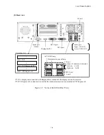
Figure 1-2 Name of Each Part (Rear View) ............................................................................... 1-6
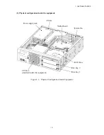
Figure 1-3 Physical Configuration Inside Equipment ................................................................ 1-7
Figure 1-4 Operation and Service Clearance (Top View) ....................................................... 1-15
Figure 1-5 Installation Clearance ............................................................................................. 1-15
Figure 1-6 Exterior View (Horizontal Installation on the Desktop) ........................................ 1-16
Figure 1-7 Exterior View (Vertical Installation on the Desktop) ............................................ 1-16
Figure 1-8 Hardware Connection
............................................................................................. 1-18
Figure 2-1 DVD Drive (Front View) ......................................................................................... 2-5
Figure 6-1 Types and Locations of Installed Components ........................................................ 6-5
Figure 6-2 Removing the Cover of the Equipment .................................................................... 6-7
Figure 6-3 Removing the PCI Cover ......................................................................................... 6-9
Figure 6-4 Removing an extension board ................................................................................ 6-10
Figure 6-5 Installing an extension board .................................................................................. 6-11
Figure 6-6 Removing the FFC cable ........................................................................................ 6-13
Figure 6-7 Removing a main memory ..................................................................................... 6-16
Figure 6-8 Removing an HDD or SSD .................................................................................... 6-19
Figure 6-9 Removing a DVD drive .......................................................................................... 6-21
Figure 6-10 Removing a dust filter .......................................................................................... 6-22
Figure 6-11 Installing a dust filter ............................................................................................ 6-22
Figure 6-12 Attaching the vertical stand .................................................................................. 6-23
Figure 6-13 Removing the lithium battery ............................................................................... 6-24
Figure 6-14 Removing a Jumper Socket .................................................................................. 6-27
Summary of Contents for HF-W2000
Page 44: ...This Page Intentionally Left Blank ...
Page 72: ...This Page Intentionally Left Blank ...
Page 102: ...This Page Intentionally Left Blank ...
Page 133: ......
Page 134: ...This Page Intentionally Left Blank ...
Page 176: ...This Page Intentionally Left Blank ...
Page 204: ...This Page Intentionally Left Blank ...
Page 245: ...This Page Intentionally Left Blank ...
Page 279: ...This Page Intentionally Left Blank ...

