1. GETTING STARTED
1-18
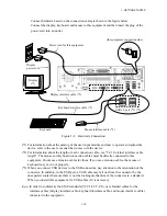
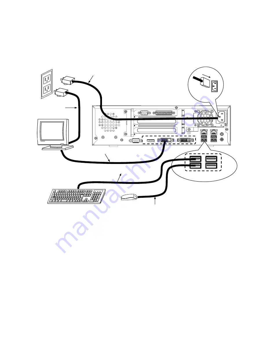
Connect hardware based on the connection example shown in the figure below.
Connect the display, keyboard, and mouse to this equipment and then insert the plug of the
power cord into an outlet.
Figure 1-8 Hardware Connection
(*1) For information about the naming of the user input module and how to operate and adjust the
device, refer to the user’s manual that comes with the device.
(*2) For information about the length of each connection cable, see “5.8.3 External interface cable
length”.
The mouse and keyboard connection cables must be directly connected to this
equipment. Do not use extension cables for them. If you use extension cables, the mouse or
keyboard may not work properly.
(*3) When you connect USB devices to the USB connectors, pay attention to the orientation of the
connector. In addition, in the USB port, a USB cable may fall out from the connector by the
unexpected contact because there is not the locking mechanism of the connector in a standard.
When you install this equipment, fix USB cables if it is necessary.
(Note)
In order to conformity the EMC standards (VCCI, FCC, CE), use shielded cables for the
interface cables (display interface cable, keyboard interface cable, and mouse interface cable)
connected to the equipment.
Mouse
Display
(*1)
Keyboard
(the equipment connection side)
Power cord for this equipment
Display
power cord
Display interface cable (*2)
Keyboard interface cable (*2)
Mouse interface cable (*2)
USB3.0 port (*2) (*3)
Summary of Contents for HF-W2000
Page 44: ...This Page Intentionally Left Blank ...
Page 72: ...This Page Intentionally Left Blank ...
Page 102: ...This Page Intentionally Left Blank ...
Page 133: ......
Page 134: ...This Page Intentionally Left Blank ...
Page 176: ...This Page Intentionally Left Blank ...
Page 204: ...This Page Intentionally Left Blank ...
Page 245: ...This Page Intentionally Left Blank ...
Page 279: ...This Page Intentionally Left Blank ...

