457
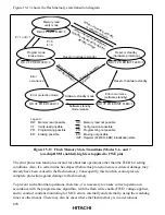
FWE=high
(user program mode)
Branch to program in RAM.
Transfer on-board programming
program to RAM.
Reset start
MD
2
to MD
0
= 101, 110, 111
Execute on-board programming
program in RAM
(flash memory reprogramming).
Input low level to FWE after SWE
bit clear (user program mode exit)
Execute user application
program in flash memory.
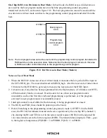
<Procedure>
The user writes a program that executes steps 3 to 8 in advance
as shown below .
Sets the mode pin to an on-chip ROM enable mode
(mode 5, 6, or 7).
Starts the CPU via reset.
(The CPU can also be started from the user program
mode by setting the FWE pin to High level during reset;
that is, during the period the RES pin is a low level.)
Transfers the on-board programming program to RAM.
Branches to the program in RAM.
Sets the FWE pin to a high level.
*
(Switches to user program mode.)
After confirming that the FWE pin is a high level, executes
the on-board programming program in RAM. This
reprograms the user application program in flash memory.
At the end of reprograming, clears the SWE bit, and exits
the user program mode by switching the FWE pin from
a high level to a low level.
*
Branches to, and executes, the user application program
reprogrammed in flash memory.
1
2
3
4
5
6
7
8
1
2
3
4
5
6
7
8
Notes: 1. Normally do not apply a high level to the FWE pin. To
prevent erroneous programming or erasing in the event
of program runaway, etc., apply a high level to the FWE
pin only when programming/erasing flash memory
(including flash memory emulation by RAM). If program
runaway, etc. causes overprogramming or overerasing
of flash memory, the memory cells will not operate
normally.
Also, while a high level is applied to the FWE pin, the
watchdog timer should be activated to prevent
overprogramming or overerasing due to program
runaway, etc.
2.
For notes on FWE pin High/Low, see section 15.11,
Notes on Flash Memory Programming/Erasing.
3. In order to execute a normal read of flash memory in
user program mode, the program/erase program must
not be executing. It is thus necessary to ensure that
bits 6 to 0 in FLMCR1 are cleared to 0.
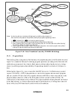
Figure 15-9 User Program Mode Execution Procedure (Example)

