275
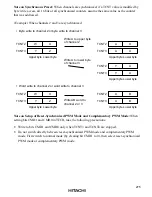
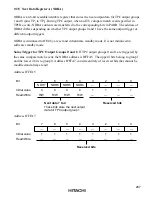
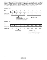
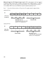
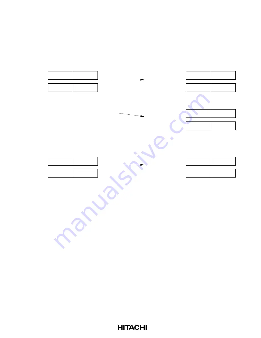
Note on Synchronous Preset: When channels are synchronized, if a TCNT value is modified by
byte write access, all 16 bits of all synchronized counters assume the same value as the counter
that was addressed.
(Example) When channels 2 and 3 are synchronized
• Byte write to channel 2 or byte write to channel 3
TCNT2
TCNT3
W
Y
X
Z
TCNT2
TCNT3
A
A
X
X
TCNT2
TCNT3
Y
Y
A
A
TCNT2
TCNT3
W
Y
X
Z
TCNT2
TCNT3
A
A
B
B
• Word write to channel 2 or word write to channel 3
Upper byte Lower byte
Upper byte Lower byte
Upper byte Lower byte
Upper byte Lower byte
Upper byte Lower byte
Write A to upper byte
of channel 2
Write A to lower byte
of channel 3
Write AB word to
channel 2 or 3
Note on Setup of Reset-Synchronized PWM Mode and Complementary PWM Mode: When
setting bits CMD1 and CMD0 in TFCR, take the following precautions:
•
Write to bits CMD1 and CMD0 only when TCNT3 and TCNT4 are stopped.
•
Do not switch directly between reset-synchronized PWM mode and complementary PWM
mode. First switch to normal mode (by clearing bit CMD1 to 0), then select reset-synchronized
PWM mode or complementary PWM mode.


