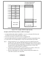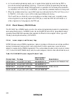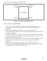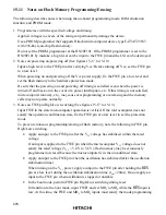
481
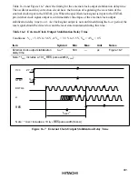
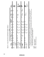
Flash memory access disabled time
(x: Wait time after SWE setting, y: Wait time after SWE clearing)
*
3
Flash memory reprogammable period
(Flash memory program execution and data read, other than verify, are disabled.)
φ
V
CC
FWE
t
OSC1
Min 0
µ
s
t
MDS
t
MDS
t
MDS
t
RESW
MD
2
to MD
0
RES
SWE bit
Mode switching
*
1
Mode
switching
*
1
Boot mode
User
mode
User
mode
User program mode
User
program
mode
SWE set
SWE clear
Prog
ramming and
er
ase possib
le
W
ait time:
x
W
ait time:
y
Prog
ramming and
er
ase possib
le
W
ait time:
x
W
ait time:
y
Prog
ramming and
er
ase possib
le
W
ait time:
x
W
ait time:
y
Prog
ramming and
er
ase possib
le
W
ait time:
x
W
ait time:
y
*
2
Notes: 1. In transition to the boot mode and transition from the boot mode to another mode, mode switching via
RES
input is necessary.
During this switching period (period during which a low level is input to the
RES
pin), the state of the address
dual port and bus control output signals (
AS
,
RD
,
WR
) changes.
Therefore, do not use these pins as output signals during this switching period.
2. When making a transition from the boot mode to another mode, the mode programming setup time t
MDS
relative to the
RES
clear timing is necessary.
3. See 18.2.5 Flash Memory Characteristics.
Figure 15-19 Mode Transition Timing
(Example: Boot mode
→
User mode
↔
User program mode)

