51
2.8.5 Reset State
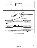
When the
RES
input goes low all current processing stops and the CPU enters the reset state. The I
bit in the condition code register is set to 1 by a reset. All interrupts are masked in the reset state.
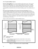
Reset exception handling starts when the
RES
signal changes from low to high.
The reset state can also be entered by a watchdog timer overflow. For details see section 10,
Watchdog timer.
2.8.6 Power-Down State
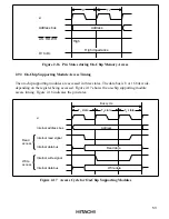
In the power-down state the CPU stops operating to conserve power. There are three modes: sleep
mode, software standby mode, and hardware standby mode.
Sleep Mode: A transition to sleep mode is made if the SLEEP instruction is executed while the
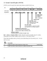
SSBY bit is cleared to 0 in the system control register (SYSCR). CPU operations stop
immediately after execution of the SLEEP instruction, but the contents of CPU registers are
retained.
Software Standby Mode: A transition to software standby mode is made if the SLEEP
instruction is executed while the SSBY bit is set to 1 in SYSCR. The CPU and clock halt and all
on-chip supporting modules stop operating. The on-chip supporting modules are reset, but as long
as a specified voltage is supplied the contents of CPU registers and on-chip RAM are retained.
The I/O ports also remain in their existing states.
Hardware Standby Mode: A transition to hardware standby mode is made when the
STBY
input
goes low. As in software standby mode, the CPU and clock halt and the on-chip supporting
modules are reset, but as long as a specified voltage is supplied, on-chip RAM contents are
retained.
For further information see section 17, Power-Down State.


