199
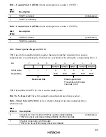
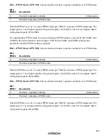
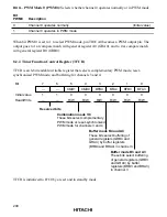
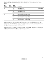
Bit 3—PWM Mode 3 (PWM3): Selects whether channel 3 operates normally or in PWM mode.
Bit 3
PWM3
Description
0
Channel 3 operates normally
(Initial value)
1
Channel 3 operates in PWM mode
When bit PWM3 is set to 1 to select PWM mode, pin TIOCA3 becomes a PWM output pin. The
output goes to 1 at compare match with general register A3 (GRA3), and to 0 at compare match
with general register B3 (GRB3).
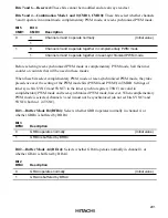
If complementary PWM mode or reset-synchronized PWM mode is selected by bits CMD1 and
CMD0 in the timer function control register (TFCR), the CMD1 and CMD0 setting takes
precedence and the PWM3 setting is ignored.
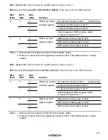
Bit 2—PWM Mode 2 (PWM2): Selects whether channel 2 operates normally or in PWM mode.
Bit 2
PWM2
Description
0
Channel 2 operates normally
(Initial value)
1
Channel 2 operates in PWM mode
When bit PWM2 is set to 1 to select PWM mode, pin TIOCA2 becomes a PWM output pin. The
output goes to 1 at compare match with general register A2 (GRA2), and to 0 at compare match
with general register B2 (GRB2).
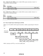
Bit 1—PWM Mode 1 (PWM1): Selects whether channel 1 operates normally or in PWM mode.
Bit 1
PWM1
Description
0
Channel 1 operates normally
(Initial value)
1
Channel 1 operates in PWM mode
When bit PWM1 is set to 1 to select PWM mode, pin TIOCA1 becomes a PWM output pin. The
output goes to 1 at compare match with general register A1 (GRA1), and to 0 at compare match
with general register B1 (GRB1).

