Page 1: ...epartment 415 592 9983 All Other Inquiries 415 592 7108 FAX 415 592 2503 or 415 595 2664 TELEX 176043 Answer Back JAMECO BLMT Printed in Taiwan Jameco IIII ELECTRONICS I _ _ r t I CJ I J I r rJllJ IqI...
Page 2: ...JEI049 Four Floppy Disk Controller Card User s Manual 1IB DOC Revision 1 203 March 15 19B9 Copyright 19B9 Jameco ElectrOnics...
Page 3: ...ons to this equipment it is the responsibility of the user to correct such interference If necessary the user should consult the dealer or an experienced radio television technician for additional sug...
Page 4: ...s JE1049 Diagram 3 Data Cable Diagram 6 Drive Type Select Switch 8 Drive Cable Connection Diagram 10 IBM PC Drive Configuration Switch Settings 4 IBM PC XT Drive Configuration Switch Settings 5 BIOS A...
Page 5: ...s with the JEI049 JE1049 floppy disk drive controller card 34 pin floppy disk drive control data cable 1 4 Terminology Throughout this manual a variety of common computer terms and abbreviations will...
Page 6: ...ter DOS will consider it to be both logical drive A and logical drive B fyou have two floppy disk drives installed in your computer DOS will consider the first to be logical drive A and the second to...
Page 7: ...1 Tum the computer on It will start to go through a power on self test POSf 2 As soon as it appears to have finished the POST and before the computer accesses the drives hit ill Release all three 5 T...
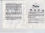
Page 8: ...type of floppy disk drives that will be connected to the JE1049 floppy disk drive controller card The switch blockis divided into four pairs A B C and D representing the drive deSignators A B C and D...
Page 9: ...be installed in an IBM AT or compatible it will not matter if it is installed in a short 8 bit slot or the lo er I6 bit slots 2 4 7 Remove the back plane bracket for the slot selected if applicable S...
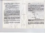
Page 10: ...ock labeled DS1 2 4 15 Install a DOS diskette in drive A and turn the computer on Try to format a blank diskette in drive A Ifyou have other floppy disk drives try to format thein too If you have any...
Page 11: ...nted on wrong part of cable Two floppy controllers installed 13 4 1 4 Two or more disk drives are installed in the system and all drives become active at the same time Check to verify that both disk d...
Page 12: ...ossible Address correspondence to JAMECO ELECTRONICS 1355 Shoreway Road Belmont CA 94002 ATTN Technical Support 15 GLOSSARY BIOS Basic Input Output System Normally stored in ROM BIOS routines provide...
Page 13: ...this memory as the computers scratch pad Once power is turned off to the computer the RAM contents are lost I ROM Read Only Memory This is memory that can t be changed nor would you want to When powe...