320
10.3.4 Timing of Setting of Watchdog Timer Reset Bit (WRST)
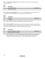
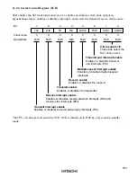
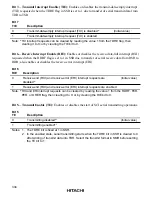
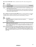
The WRST bit in RSTCSR is valid when bits WT/
IT
and TME are both set to 1 in TCSR.
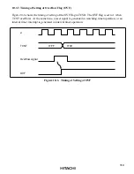
Figure 10-7 shows the timing of setting of WRST and the internal reset timing. The WRST bit is
set to 1 when TCNT overflows and OVF is set to 1. At the same time an internal reset signal is
generated for the entire H8/3022 Series chip. This internal reset signal clears OVF to 0, but the
WRST bit remains set to 1. The reset routine must therefore clear the WRST bit.
ø
TCNT
Overflow signal
OVF
WRST
H'FF
H'00
WDT internal
reset
Figure 10-7 Timing of Setting of WRST Bit and Internal Reset

