Preparing to Cut: Setting Conditions
55
1
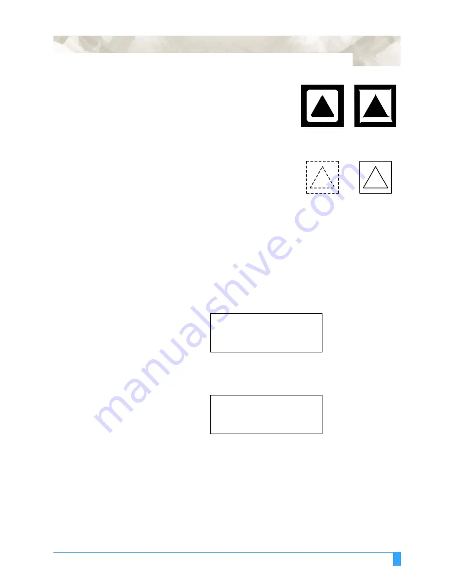
Peel off the outside triangle first to view the
shape of the corners. The corner’s shape
represents the cutter offset setting. If the cor-
ners are rounded, the cutter offset value
should be decreased; if the corners are too
sharp, the cutter offset value should be
increased.
2
Next peel off the triangle from the liner to
view the depth of the cutter trail. The depth
of the cutter trail represents the blade length.
The best setting creates a light scratch on
the liner.
3
If the scratch is too light and the trail breaks
in places, increase the blade length; if the scratch is so heavy that it cuts the
liner, the blade should be shortened.
4
Change the parameters as needed.
5
Repeat steps 1 through 3 until the test results are satisfactory.
Test 1
Use this TEST 1 triangle pattern to test your condition settings. With the media
loaded in the plotter and the READY mode displayed on the menu, press the TEST
key on the control panel.
You will see the following test menu:
Press the F2 key to select TEST 1.
The plotter will immediately cut one (1) triangle from the current pen position.
• Adjust the cutting conditions and re-run the cutting test.
• Repeat this process until you achieve the desired results.
• Press the ENTER key to return to the READY mode when the results are satis-
factory.
CONDITION 1
........
14
.
30
.
READY
.............
4
.
CB09Ux
...
0
.
TEST 1>
.
TEST 2>
.
CUTTING PRO>
.
Summary of Contents for FC5100A-100
Page 1: ...A 75 100 130 150 user manual MANUAL NO FC5100 UM 154...
Page 3: ......
Page 11: ......
Page 27: ...Out of the Box Connecting the Plotter 27...
Page 33: ...Cutters and Holders Blade Length 33...
Page 133: ...Advanced Functions and Settings RS 232C Serial Interface 133...
Page 149: ...Background Settings Background Settings for HP GL 149...


