Preparing to Cut: Control Panel
34
Chapter 4: Preparing to Cut
This chapter describes how to use the control panel, load the media, select and install the appro-
priate cutting tools, and to achieve the best cutting results.
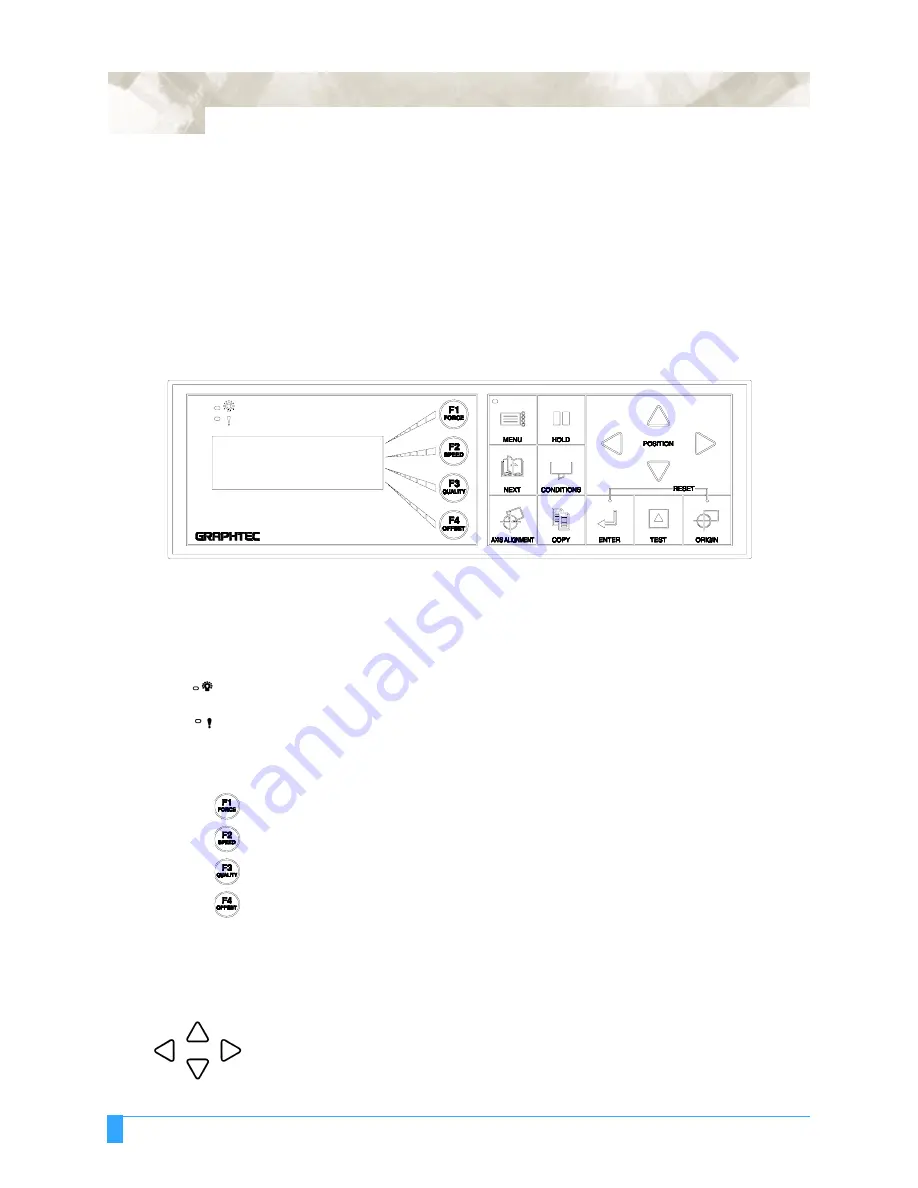
Control Panel
Indicator Lamps
The POWER lamp remains lit (green) while the plotter is on.
The PROCESSING INDICATOR lamp lights green when the cutting data goes
beyond the effective cutting area.
Function Keys
These four keys [F1, F2, F3 and F4] have functions which change as each menu
changes. Depending on the menu being displayed, these keys are used to:
• Load a group of cutting conditions retained in the plotter’s memory
• Select the desired submenu
• Select the desired parameters
Position Keys
All four keys are used to move the pen carriage when setting a function that
requires the specification of a coordinate position. The moving speed of the pen
carriage can be controlled in two levels by changing pressure applied to the posi-
tion keys.
• Used to raise the displayed numeric setting of a function.
• Used to select the numeric setting of a function.
• Used to select the pen type when setting a group of cutting conditions.
• Used to shift the cursor when setting a numeric value for a function.
Summary of Contents for FC5100A-100
Page 1: ...A 75 100 130 150 user manual MANUAL NO FC5100 UM 154...
Page 3: ......
Page 11: ......
Page 27: ...Out of the Box Connecting the Plotter 27...
Page 33: ...Cutters and Holders Blade Length 33...
Page 133: ...Advanced Functions and Settings RS 232C Serial Interface 133...
Page 149: ...Background Settings Background Settings for HP GL 149...


