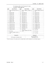
Functions 12. I/O Remote Settings
134
RC700-D Rev.2
12.2.4 Timing Diagram for Safety Door Input Sequence
8
1052
1052
500
9
11
11
928
Running
Output
Paused
Output
SafeguardOn
Output
MotorsOn
Output
SD Signal
(*1)
SDLATCH
Signal (*1)
Continue
Input
[Unit: msec]
(*1) A logical signal to explain the timing of internal processing of the controller.
For details about input signals name and operating conditions, refer to the
9.3 Pin
Assignments.
12.2.5 Timing Diagram for Emergency Stop Sequence
920
7
5
Running
Output
MotorsOn
Output
EStopOff
Output
ESW Signal
(*1)
Reset Signal
Input
7
[Unit: msec]
(*1) A logical signal to explain the timing of internal processing of the controller.
For details about input signals name and operating conditions, refer to the
9.3 Pin
Assignments.
Summary of Contents for RC700-D
Page 1: ...Control Unit RC700 D Original instructions Rev 2 EM221C5146F ROBOT CONTROLLER RC700 D Manual ...
Page 2: ...ROBOT CONTROLLER RC700 D Manual Rev 2 ...
Page 8: ...vi RC700 D Rev 2 ...
Page 16: ...Table of Contents xiv RC700 D Rev 2 ...
Page 18: ......
Page 80: ...Installation 5 Second Step 64 RC700 D Rev 2 ...
Page 82: ......
Page 87: ...Functions 1 Specifications RC700 D Rev 2 71 1 3 Outer Dimensions Unit mm ...
Page 190: ......
Page 202: ...Regular Inspection 3 Alarm 186 RC700 D Rev 2 ...
Page 203: ...187 Appendix ...
Page 204: ......


