


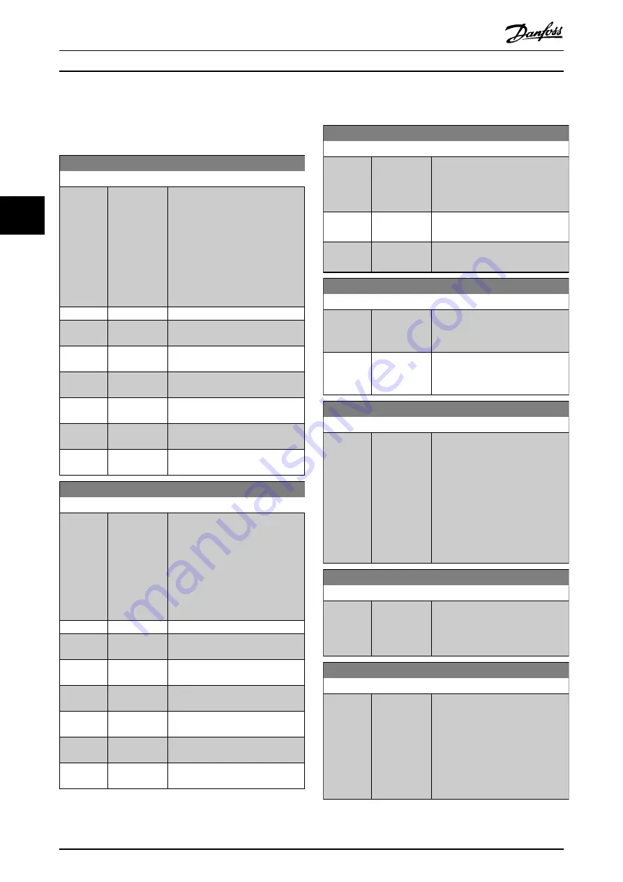
4.8.2 7-2* Process Ctrl. Feedb.
Select the feedback sources for the process PID control,
and how this feedback should be handled.
7-20 Process CL Feedback 1 Resource
Option:
Function:
The effective feedback signal is
made up of the sum of up to 2
different input signals.
Select which frequency converter
input should be treated as the
source of the 1
st
of these signals.
The 2
nd
input signal is defined in
parameter 7-22 Process CL Feedback
2 Resource
.
[0]
*
No function
[1]
Analog Input
53
[2]
Analog Input
54
[3]
Frequency
input 29
[4]
Frequency
input 33
[7]
Analog Input
X30/11
[8]
Analog Input
X30/12
7-22 Process CL Feedback 2 Resource
Option:
Function:
The effective feedback signal is
made up of the sum of up to 2
different input signals. Select which
frequency converter input should
be treated as the source of the 2
nd
of these signals. The 1
st
input signal
is defined in
parameter 7-20 Process
CL Feedback 1 Resource
.
[0]
*
No function
[1]
Analog Input
53
[2]
Analog Input
54
[3]
Frequency
input 29
[4]
Frequency
input 33
[7]
Analog Input
X30/11
[8]
Analog Input
X30/12
4.8.3 7-3* Process PID Ctrl.
7-30 Process PID Normal/ Inverse Control
Option:
Function:
Normal and inverse controls are
implemented by introducing a
difference between the reference
signal and the feedback signal.
[0]
*
Normal
Set process control to increase the
output frequency.
[1]
Inverse
Set process control to decrease the
output frequency.
7-31 Process PID Anti Windup
Option:
Function:
[0]
Off
Continue regulation of an error
even when the output frequency
cannot be increased or decreased.
[1]
*
On
Cease regulation of an error when
the output frequency can no longer
be adjusted.
7-32 Process PID Start Speed
Range:
Function:
0 RPM
*
[0 - 6000
RPM]
Enter the motor speed to be
attained as a start signal for
commencement of PID control.
When the power is switched on,
the frequency converter starts to
ramp and then operates under
speed open-loop control. When the
process PID start speed is reached,
the frequency converter changes to
process PID control.
7-33 Process PID Proportional Gain
Range:
Function:
0.01
*
[0 - 10 ]
Enter the PID proportional gain. The
proportional gain multiplies the
error between the setpoint and the
feedback signal.
7-34 Process PID Integral Time
Range:
Function:
10000 s
*
[0.01 - 10000
s]
Enter the PID integral time. The
integrator provides an increasing
gain at a constant error between
the setpoint and the feedback
signal. The integral time is the time
needed by the integrator to reach
the same gain as the proportional
gain.
Parameter Descriptions
VLT® AutomationDrive FC 361
90
Danfoss A/S © 03/2019 All rights reserved.
MG06J202
4
4
Summary of Contents for VLT AutomationDrive FC 361
Page 2: ......


