SRV-63 series AC servo drives Detailed parameter description
-90-
0
1
1
P0.49
Internal speed 4
1
0
0
P0.50
Internal speed 5
1
0
1
P0.51
Internal speed 6
1
1
0
P0.52
Internal speed 7
1
1
1
P0.53
Internal speed 8
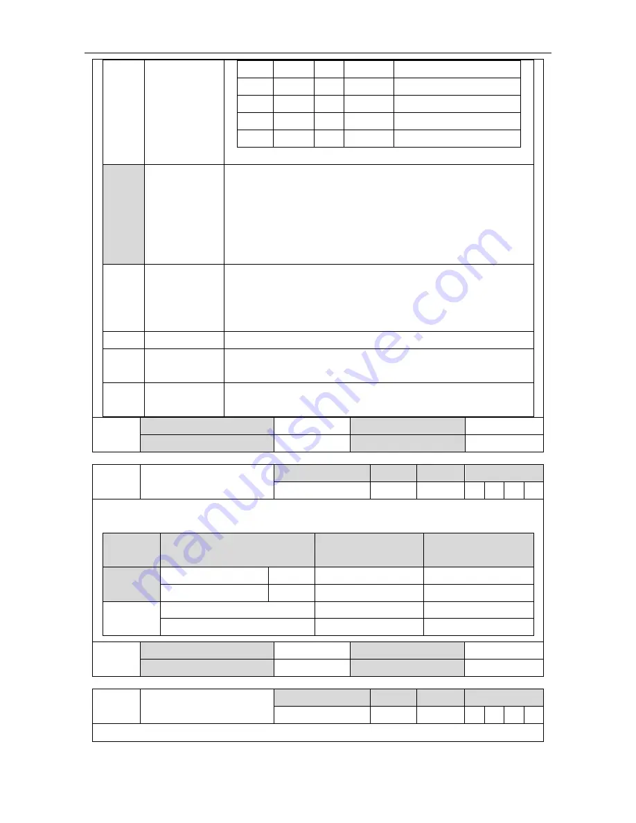
Please refer to the detailed instruction of P0.46~P0.53.
[1]
Analog input
The motor speed can be controlled by applying -10V~10V voltage
between analog speed input terminals (AD1, GND, pin “1” and “5”)
of CN1. In the factory default, the positive value means the forward
direction and the negative value means the reverse direction.
The direction of analog speed command can be changed by P0.41.
Please refer to the detailed instruction of P0.41.
2
Bus input
The speed command from upper PC can be received by the
interface of communication bus. When P4.10 is 1, the motor speed
can be changed by P4.13.
Please refer to the detailed instruction of P4.10 and P4.13.
3
Factory use -
4
2
nd
encoder
input
The speed is the speed calculated via P0.22 of 2
nd
encoder pulse.
5
High resolution
internal speed
High resolution internal speed, precision 0.1r/min
P0.40
Data size
16bit
Data format
DEC
Modbus address
1080,1081
CANopen address
0x2028, 0x00
P0.41
Setting of speed command
direction
Setting range
Default
Unit
Available mode
0~1
0
-
S
This parameter is used to set the forward/reverse direction when P0.40 is 0 and 1 and the speed
command sign is selected as S-SIGN.
Setting
value
Internal speed step/analog input Speed command sign
Speed command
direction
[0]
Positive speed
0V ~10V
No use
Forward direction
Negative speed
-10V~0V
No use
Reverse direction
1
No use
Valid
Forward direction
No use
Invalid
Reverse direction
P0.41
Data size
16bit
Data format
DEC
Modbus address
1082,1083
CANopen address
0x2029, 0x00
P0.42
Analog input 1 gain
Setting range
Default
Unit
Available mode
10~2000
100
(r/min)/V
S
1. Suppose the analog input 1 function selection is speed command.


