SRV-63 series AC servo drives Control mode applications
-54-
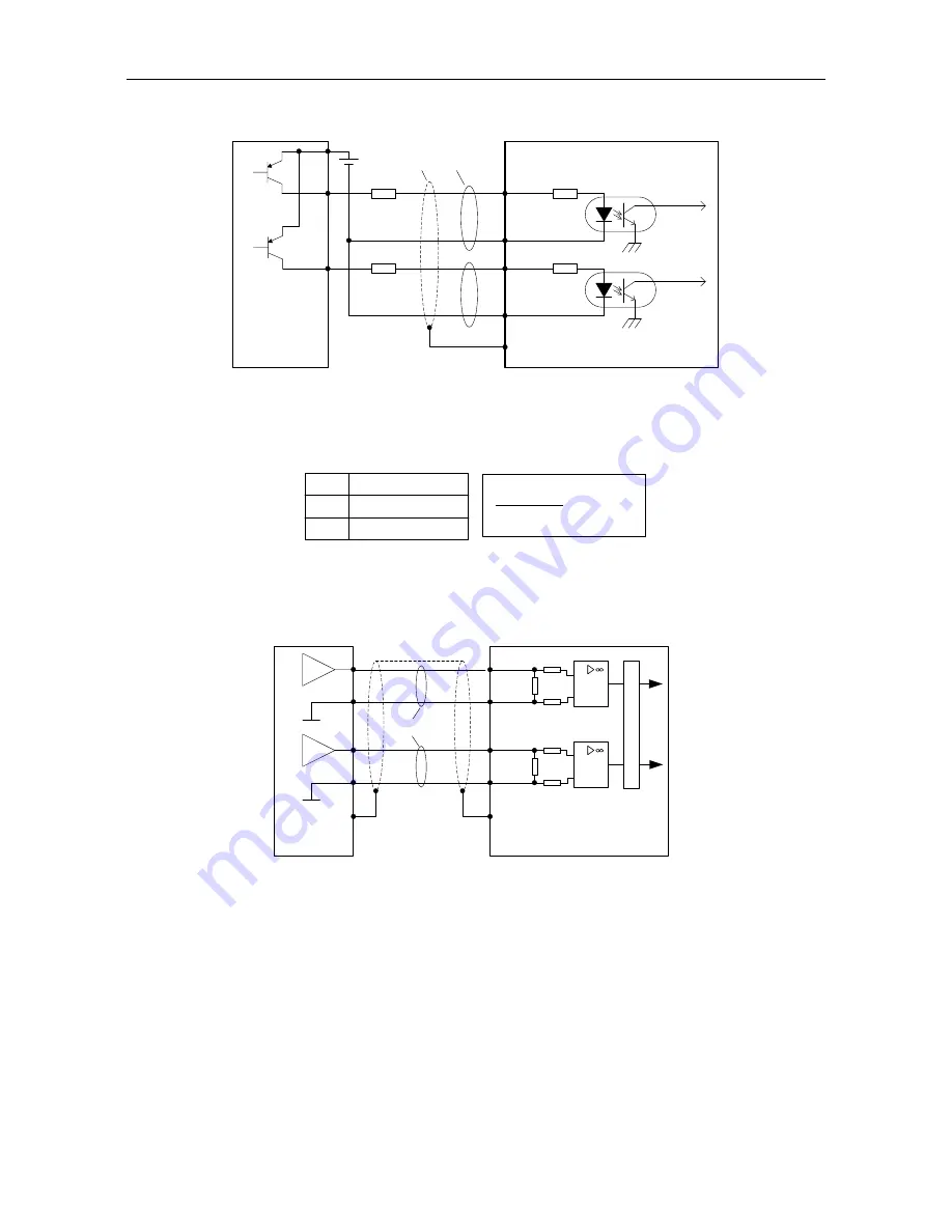
The control module is PNP (common anode):
Control module
side
Drive side
23 PULS+
24 PULS-
33 SIGN-
FG
Y1
Y0
PULS
SIGN
32 SIGN+
+
-
R
R
Shielded
cable
DC12~24V
Twisted
pair
The input pulse frequency is 200kHz; if the local 24V power supply (it only can provide 100mA
current) or the 12~24V power supply provided by the user is used, it is required to connect to
current-limiting resistor R(the resistance is selected as the below table).
V
DC
-1.5
R+68
≈
10(mA)
V
DC
R parameter
12V 1k
Ω,1/4W
24V
2k
Ω,1/3W
For all the 3 methods, shielded twisted-pair must be used and the length should be less than 3m.
4.5.3 Wiring of the analog input circuit
0
0
0
1 AD1
5 GND
20 AD2
A
D
C
FG
Please connect shielded
cable according to the
device requirement
Twisted
pair
19 GND
0
0
0
Drive side
Control module
side
There are three analog input circuits, AD1, AD2 and AD3, precision of AD1 is 16-bit (optional for
standard models), precision of AD2 and AD3 is 12-b
it (standard). The input impedance is 10kΩ.
The input voltage range is -
10V~+10V. If the voltage is higher than ±11V, the circuits may be
damaged.
If the non-standard model is used as the speed control, AD1 channel is invalid, please take AD3
as the speed command input
terminal and modify P3.70 to “speed command”.


