


Chapter 4
69
Preparation of Measurement Accessories
Adapter Setting
4
. P
re
par
ati
on
of
M
eas
ur
em
en
t A
cce
ss
or
ie
s
NOTE
Adapter selection status can also be confirmed through the display of the instrument status
area on the LCD's left side. Refer to “Adapter type” on page 58.
Step 3.
Press
ADAPTER [ ]
key to display the Adapter Setting Menu.
Step 4.
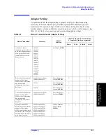
Select the corresponding adapter selection from the following:
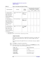
Adapter Setup
The adapter setup is a process used to acquire the setup data of the adapter selected by the
“Adapter Selection” on page 68. The adapter setup is normally performed in the following
cases.
•
When using the 16048G with the Agilent 4294A for the first time after it is delivered.
•
When using the 16048H with the Agilent 4294A for the first time after it is delivered.
•
When using the 16334A with the Agilent 4294A for the first time after it is delivered.
•
When using the 16451B with the Agilent 4294A for the first time after it is delivered.
•
When using the 42942A with the Agilent 4294A for the first time after it is delivered.
•
When using the 42941A with the Agilent 4294A for the first time after it is delivered.
•
When making a measurement in an ambient temperature that is outside the range of
±
5
°
C from the adapter setup temperature for the above accessories.
NOTE
Generally, the adapter setup does not need to be performed except for the above cases.
For each adapter setup procedure, refer to:
•
“Adapter Setup Procedure for the 16048G and 16048H” on page 70
•
“Adapter Setup Procedure for the 16334A” on page 72
•
“Adapter Setup Procedure for the 16451B” on page 73
•
“Adapter Setup Procedure for the 42942A” on page 74
•
“Adapter Setup Procedure for the 42941A” on page 78
ADAPTER [PROBE]
42941A Impedance Probe
Adapter Selection
Key Strokes
No Adapter
NONE
Four-terminal pair, 1 meter
4TP 1M
Four-terminal pair, 2 meters
4TP 2M
42942A Terminal Adapter
7mm 42942A
42941A Impedance Probe
PROBE 42941A
Softkey Label
Adapter Selection Status
Summary of Contents for 4294A
Page 1: ......
Page 2: ......
Page 4: ......
Page 5: ......
Page 6: ......
Page 8: ......
Page 16: ...8 ...
Page 30: ...22 Chapter1 Installation Power Cable Figure 1 2 Alternative Power Cable Options ...
Page 70: ...62 Chapter3 Front Rear Panel and LCD Display Items Displayed on the LCD ...
Page 436: ...428 AppendixB Key Definitions Softkeys displayed by pressing the Recall key ...
Page 454: ...446 AppendixC Error messages WRONG I O PORT DIRECTION ...
Page 468: ......


